
Vehicle window roller shutter driving device preventing sliding deflection and using method thereof
A driving device and rolling shutter technology, applied in the direction of door/window protection device, window, window/door, etc., can solve the problem of easy interference with the vehicle body in the movement space of the rack, and achieve the purpose of avoiding interference movement, convenient use and shortening. The effect of size
- Summary
- Abstract
- Description
- Claims
- Application Information
AI Technical Summary
Problems solved by technology
Method used
Image

Examples
Embodiment Construction
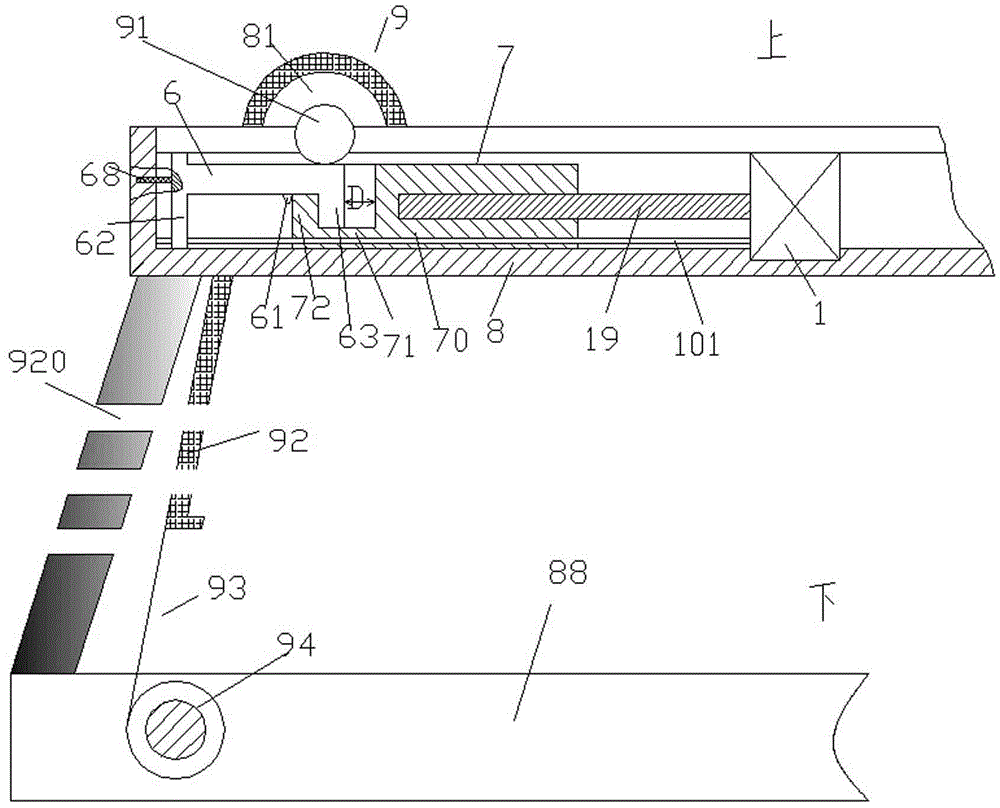
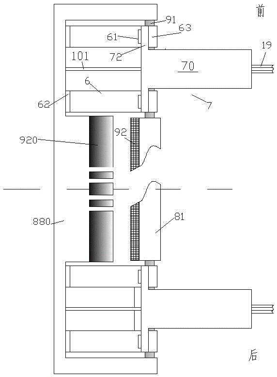
[0012] Combine below Figure 1-2 The present invention will be described in detail.
[0013] A vehicle window roller blind driving device for preventing sliding deviation according to an embodiment, comprising a fixing frame part 8 fixed on a vehicle body 88, and a roller blind assembly 9 pivotable relative to the fixing frame part 8, the The roller blind assembly 9 includes a roller blind reel 81 for being fixedly connected with the upper end of the roller blind 92 and capable of winding the roller blind 92, and a drive shaft type coaxially arranged at the front and rear sides of the roller blind reel 81 symmetrically. A gear 91, and a biased pivot wheel 94 fixedly connected to the lower end of the roller blind by a flexible pull cable, the biased pivot wheel 94 is biased by a pivot bias spring to direct the roller blind 92 toward The lower part is tightened; two rack drive assemblies symmetrically positioned at the front and rear sides of the shutter reel 81 are arranged in...
PUM
 Abstract
Description
Claims
Application Information