Lockable quick-fit sealing structure for small diameter tubular structure

A technology for sealing structure and structure, which is applied in the direction of sealing surface connection, pipe/pipe joint/pipe fitting, passing components, etc. It can solve the problems of general resilience of metal gaskets, complicated installation process, position error, etc., and achieve sealing ring deformation The effect of high volume control precision and high control precision

Active Publication Date: 2018-01-02
NUCLEAR POWER INSTITUTE OF CHINA
View PDF7 Cites 0 Cited by
  • Summary
  • Abstract
  • Description
  • Claims
  • Application Information

AI Technical Summary

Problems solved by technology

[0003] For tubular structural parts such as detectors or thermocouple protection tubes, a tube seat is generally set on the pressure vessel or the primary circuit pipeline, and the tubular structural part is inserted and positioned on the tube seat, between the tubular structural part and the tube seat Set the sealing structure. The widely used sealing structure is generally divided into two types: mandatory sealing and self-tightening sealing. The mandatory sealing is provided by the fastener and the thread of the pipe seat to provide pre-tightening force to compress the metal gasket. The disadvantage of the structure is that the resilience of the metal gasket is average. As the temperature and pressure of the reactor change, the sealing structure is prone to leakage; the structure of the self-tightening seal is generally more complicated, and the installation process is also more complicated. The complicated structure and installation The process can cause position error during assembly of the complex sealing structure, the deviation between the actual pressing force and the theoretical pressing force is large, and the sealing ring is prone to excessive or undercompression, all of which will affect the current situation. With the sealing effect of self-tightening seal, the pressure vessel or pressure pipeline has a greater hidden danger of leakage

Method used


Image

  • Lockable quick-fit sealing structure for small diameter tubular structure
  • Lockable quick-fit sealing structure for small diameter tubular structure
  • Lockable quick-fit sealing structure for small diameter tubular structure

Examples


Embodiment 1

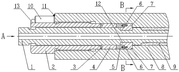
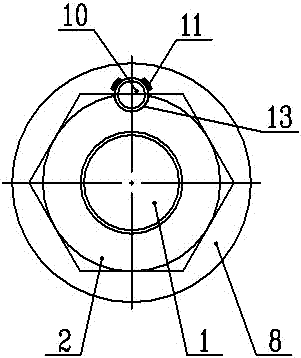
[0032] Such as Figure 1 to Figure 3 As shown, the small-diameter tubular structure uses a lockable quick-fit sealing structure, which is used for static sealing of the socket 8 at the connection point between the connecting pipe 1 and the pressure vessel or pressure pipeline, and the sealing structure includes a separating half ring 7 , sealing ring 4, hollow bolt 2;

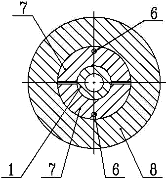
[0033]There are at least two separated half-rings 7, and an annular groove 12 is arranged on the side where the connecting pipe 1 goes deep into the pipe seat 8, and the separating half-ring 7 is arranged in the annular groove 12, and the outer side of the separating half-ring 7 is opposite to the connecting pipe 1 The outer wall surface is convex;

[0034] The hollow bolt 2 is provided with a through hole for the connecting pipe 1 to pass through, the axis of the through hole is collinear with the axis of the hollow bolt 2, and the through hole and the connecting pipe 1 are in a clearance fit relationship;

...

Embodiment 2

[0041] The present embodiment is further limited on the basis of embodiment 1, as Figure 1 to Figure 3 As shown, when the sealing structure is assembled, the separation half ring 7 is embedded in the annular groove 12 by the outside of the ring groove 12, so that when the connecting pipe 1 equipped with the separation half ring 7 is inserted into the socket 8, the separation half ring The ring 7 has the risk of falling out of the annular groove 12. When the separated half-ring 7 passes through the sealing area of ​​the tube seat 8, if it scratches the sealing surface of the sealing area, it will inevitably affect the sealing reliability of the sealing structure. , in order to eliminate the above-mentioned hidden dangers, it also includes a restricting ring 5 sleeved on the connecting pipe 1, the restricting ring 5 is located between the sealing ring 4 and the separation half-ring 7, and the end of each separation half-ring 7 close to the restricting ring 5 is At least one con...

Embodiment 3

[0049] This embodiment further limits this case on the basis of any one of the technical solutions provided by any of the above embodiments: Figure 1 to Figure 3 As shown, in order to accurately control and realize the deformation of the sealing ring 4 in the sealing state of the sealing structure, when the sealing ring 4 is in the compressed state, the end faces of the nuts of the hollow bolts 2 are in contact with the outer surface of the pipe seat 8 . In the above structure, when the separating half-ring 7 is in contact with the step surface of the step circular hole, the end of the sealing ring 4 deep into the tube seat 8 receives the supporting force, and when the hollow bolt 2 has an interaction force on the sealing ring 4, the hollow bolt 2 bolts The distance between the end face of the cap end and the pipe seat 8 is equal to the axial design compression amount of the sealing ring 4 to realize it. Namely: with this solution, the hollow bolt 2 is bonded to the pipe seat...


PUM


Abstract

The invention discloses a lockable quick-installation sealing structure for a small-diameter tubular structure. The sealing structure is used for static sealing of the pipe seat at the connection point between the connecting pipe and the pressure vessel or pressure pipeline. The sealing structure includes a separating half ring , a sealing ring, and a hollow bolt; there are at least two separate half-rings, and an annular groove is provided on the side where the connecting pipe goes deep into the socket; the hollow bolt is provided with a through hole for the connecting pipe to pass through, and the axis of the through hole It is collinear with the axis of the hollow bolt, and the through hole and the connecting pipe are in a clearance fit relationship; the sealing ring is sleeved on the connecting pipe, and the sealing ring is located between the hollow bolt and the separation half ring. When the hollow bolt penetrates into the pipe seat, The sealing ring can be squeezed and deformed. The sealing structure has the advantages of simple structure, convenient installation, high sealing reliability and easy popularization.

Description

technical field [0001] The invention relates to the technical field of a sealing structure used for nuclear reactor core measurement and primary circuit pipeline temperature measurement tubular structure, in particular to a lockable quick-install sealing structure for a small-diameter tubular structure. Background technique [0002] Since the nuclear reactor core measurement system needs to measure the core outlet temperature, the core neutron fluence rate or the core water level, and some primary circuit pipelines need to measure the reactor inlet and outlet temperature, so the reactor pressure vessel or pipeline Tubular structural members such as detectors or thermocouple protection tubes are set up to measure the above parameters. [0003] For tubular structural parts such as detectors or thermocouple protection tubes, a tube seat is generally set on the pressure vessel or the primary circuit pipeline, and the tubular structural part is inserted and positioned on the tube...

Claims


Application Information

Patent Timeline
Patent Type & Authority Patents(China)
IPC IPC(8): F16L19/03
CPCF16L19/0218
Inventor 饶琦琦许斌王留兵陈训刚罗英张宏亮刘晓李燕段春辉李娜蒋兴钧赵伟李浩
Owner NUCLEAR POWER INSTITUTE OF CHINA
Why Eureka
Try Eureka