
Method and device for precise distribution of heat supply

A distribution method and heat supply technology, applied in heating methods, heating systems, household heating, etc., can solve the problems of circulating pumps and boiler design capacity and actual capacity exceeding the error, no adjustment, uneven heat distribution, etc. To achieve the effect of resolving heating contradictions, improving energy saving efficiency, and avoiding heating accidents

Active Publication Date: 2019-06-07
呼和浩特市鸿坤热力有限责任公司
View PDF6 Cites 0 Cited by
  • Summary
  • Abstract
  • Description
  • Claims
  • Application Information

AI Technical Summary

Problems solved by technology

It will cause frequent heating accidents. When the outdoor temperature changes sharply (increase or decrease), with the traditional heating technology, the operation adjustment of the heating boiler lags behind and cannot be adjusted in time and in real time, resulting in frequent heating accidents
[0005] Traditional heat supply technology, and there is no precise control method and technology for production, transportation and distribution of heat, which makes it difficult to achieve temperature (heat) distribution. Not up to standard), uneven heat distribution
[0006] In the traditional heating technology, the heat load is operated according to the theoretical data provided by the design unit (such as the design institute) that designs the heating system. The heat load of this theoretical data is very different from the actual heat load of the actual operation of the heating system. At the same time, The installation process of heating equipment varies from good to bad. The construction of the heating pipe network is limited by geographical conditions. It is necessary to bypass various municipal pipelines. The heat load error caused the design intention of the heating system to fail to be realized, and there was no technology to adjust the error and correct the heat load operation; at the same time, the design capacity and actual capacity of the circulating pump and boiler exceeded the error range, and "pull a trolley or a pony" appeared "pull the cart" situation

Method used


Image

  • Method and device for precise distribution of heat supply
  • Method and device for precise distribution of heat supply
  • Method and device for precise distribution of heat supply

Examples


Embodiment Construction

[0028] Typical embodiments embodying the features and advantages of the present invention will be described in detail in the following description. It should be understood that the present invention is capable of various changes in different embodiments without departing from the scope of the present invention, and that the description and drawings therein are illustrative in nature and not limiting. this invention.

[0029] First, let me introduce the explanation of terms in this manual:

[0030] 1. Indoor temperature of heat users: When detecting indoor temperature, the center of the diagonal line of the house should be 1.2 meters to 1.5 meters above the ground as the detection point, and it is qualified to reach 18 ℃ in a detection period of 24 hours (source : Urban Heating Regulations of Inner Mongolia Autonomous Region).

[0031] 2. Operational efficiency of the heat exchange station: the percentage of the heat exchange station’s useful energy to the total heat of the h...


PUM


Abstract

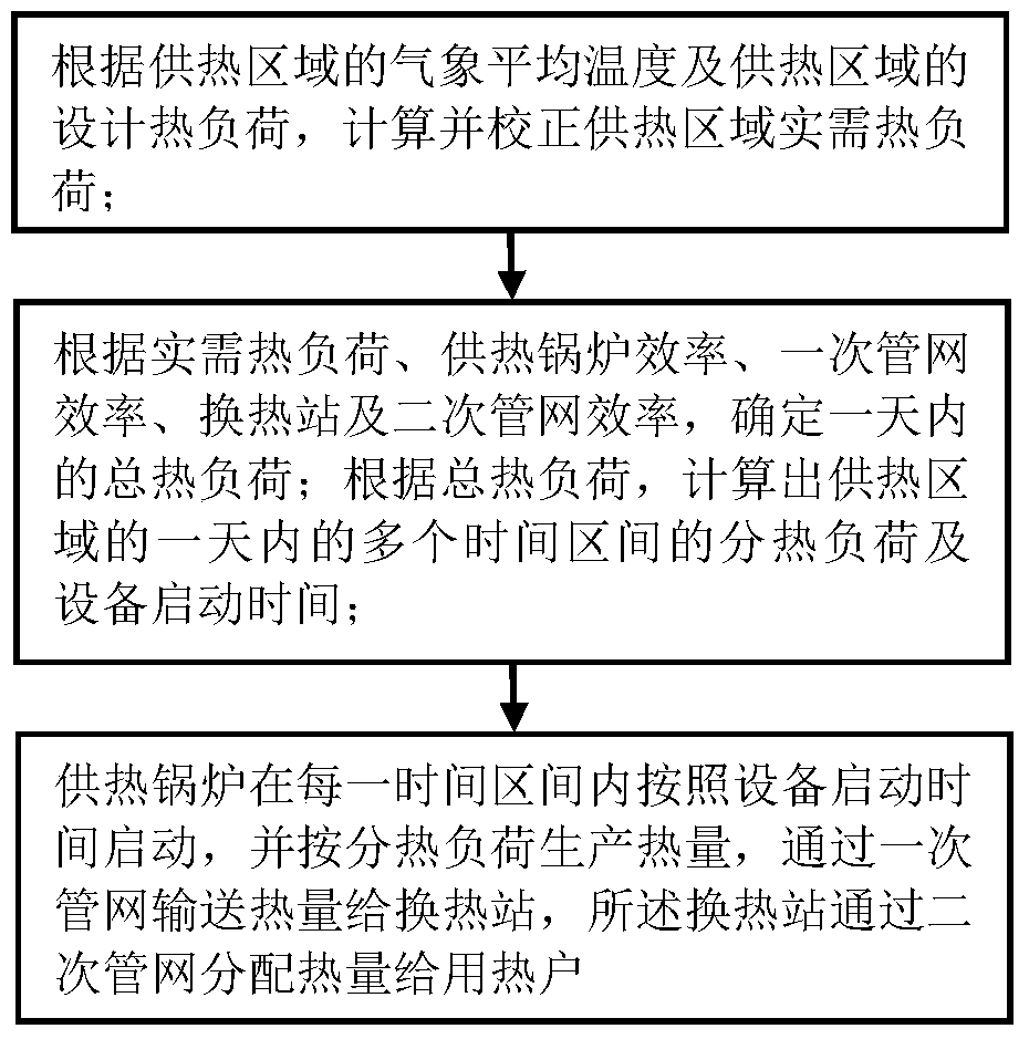
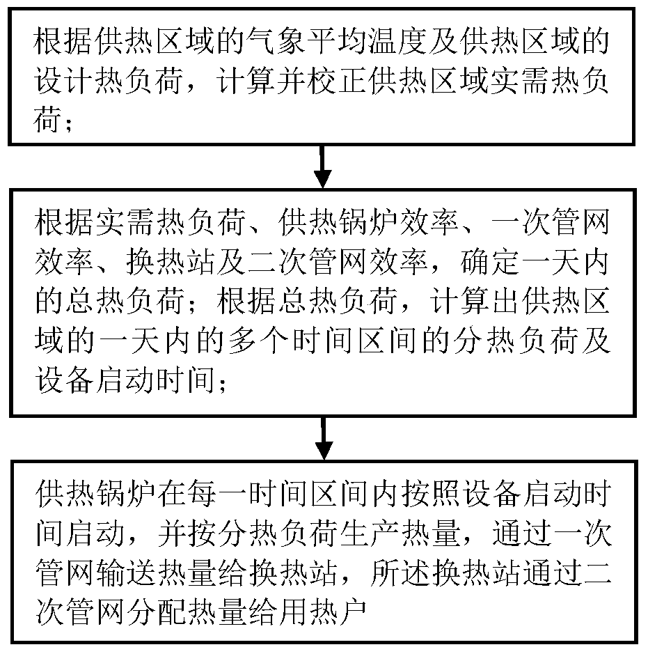
The invention discloses an accurate supply heat distribution method and an accurate supply heat distribution device. The accurate supply heat distribution method comprises the following steps: according to the atmosphere average temperature and design heat load of a heat supply region, calculating and revising actually required heat load of the heat supply region; according to the actually required heat load, heating boiler efficiency, primary pipe network efficiency, heat exchange station efficiency and secondary pipe network efficiency, determining the total heat load of one day; according to the total heat load, calculating min heat load and equipment starting time of multiple time intervals in one day of the heat supply region; and starting a heating boiler according to the equipment starting time within each time interval, generating heat according to the min heat load, conveying heat to a heat exchange station by virtue of a primary pipe network, distributing to heat users through a secondary pipe network by virtue of the heat exchange station. The accurate supply heat distribution method and the accurate supply heat distribution device are capable of solving the energy waste problem, are accurate in metered production, accurate in metered conveying and accurate in metered distribution due to metered heat usage, and are capable of achieving the purposes of saving water, electricity, coals, fuel gas and oil.

Description

technical field [0001] The invention relates to the technical field of heat supply, in particular to a method for precisely distributing heat and a device for precisely distributing heat. Background technique [0002] Heat is a special commodity that is fleeting. The traditional heating industry does not have an accurate method for heat load production, transportation and distribution. It is all distributed based on experience. When it is sold to customers, the quality of heat supply will not meet the standard or the amount of heat supplied will exceed the standard, which will cause emissions. Exceeding the standard, energy waste occurs from time to time. The outdated control technology and quantitative methods of the traditional heating industry have caused serious energy waste, and cannot be solved fundamentally. [0003] The backward control technology in the traditional heating industry has resulted in no accurate method for heat production, transportation and distribut...

Claims


Application Information

Patent Timeline
Patent Type & Authority Patents(China)
IPC IPC(8): F24D19/10
CPCF24D19/1009
Inventor 张久明
Owner 呼和浩特市鸿坤热力有限责任公司
Learn More