Seismic-wave near-surface stratum quality factor compensation method and device

A formation quality factor and near-surface technology, applied in seismic signal processing and other directions, can solve problems such as inability to compensate seismic waves

Inactive Publication Date: 2016-05-25
蒋立
View PDF5 Cites 15 Cited by
  • Summary
  • Abstract
  • Description
  • Claims
  • Application Information

AI Technical Summary

Problems solved by technology

[0005] In view of this, the present invention provides a method and device for compensating the quality factor of the near-surface seismic wave, which can compensate the seismic wave near the surface and alleviate the problem that the seismic wave near the surface cannot be compensated in the prior art

Method used


Image

  • Seismic-wave near-surface stratum quality factor compensation method and device
  • Seismic-wave near-surface stratum quality factor compensation method and device
  • Seismic-wave near-surface stratum quality factor compensation method and device

Examples


Embodiment 1

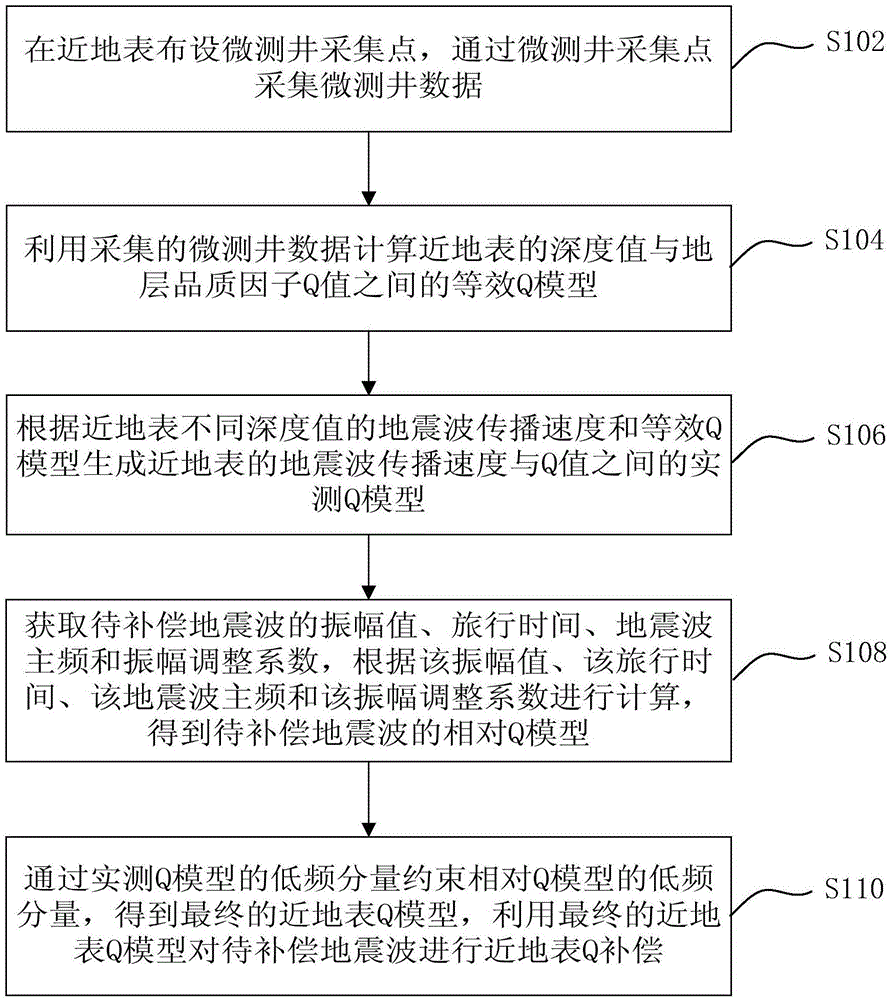
[0035] like figure 1 As shown, the first embodiment of the present invention provides a compensation method for seismic wave near-surface formation quality factor, including the following steps S102 to S110.

[0036] Step S102, laying out micro-logging collection points near the surface, and collecting micro-logging data through the micro-logging collection points; wherein, the micro-logging data includes seismic wave data.

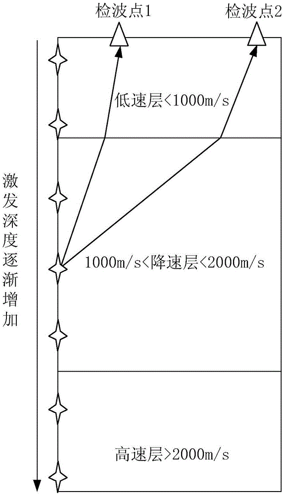
[0037] In this step, the field micro-logging construction method is as follows: figure 2 as shown, figure 2 Middle detection point 1 and detection point 2 represent the receiving points of micro-logging data. The micro-logging data is collected by stimulating surface reception in the well. In order to ensure the accuracy of the micro-logging data, the depth of the well is preferably 15-20m through the bottom interface of the low-speed zone, and detonators at equal intervals (such as figure 2 as shown by the star symbol in ), multiple detectors are ...

Embodiment 2

[0078] Corresponding to the method in Embodiment 1, such as Figure 6 As shown, the second embodiment of the present invention also provides a compensation device for seismic wave near-surface formation quality factor, including:

[0079] The micro-logging module 61 is used to arrange micro-logging collection points near the surface, and collect micro-logging data through the micro-logging collection points;

[0080] The equivalent Q model calculation module 62 is used to calculate the equivalent Q model between the depth value near the surface and the formation quality factor Q value by using the collected micro-logging data;

[0081] The measured Q model calculation module 63 is used to generate the measured Q model between the seismic wave propagation velocity and the Q value near the surface according to the seismic wave propagation velocity and the equivalent Q model of different depth values ​​near the surface;

[0082] Relative to the Q model calculation module 64, it ...


PUM


Abstract

The invention provides a seismic-wave near-surface stratum quality factor compensation method and device. The method comprises: setting micro-logging acquisition points near the earth surface and acquiring micro-logging data via the micro-logging acquisition points; calculating an equivalent Q model between a depth value near the earth surface and the stratum quality factor Q value by using the micro-logging data; generating a measured Q model between the seismic-wave propagation velocity near the earth surface and the Q value according to the seismic-wave propagation velocity at different depths near the earth surface and the equivalent Q model; calculating a relative Q model of the to-be-compensated seismic wave in accordance with the amplitude value, the travel time, the seismic-wave main frequency and the amplitude adjustment coefficient of the to-be-compensated seismic wave; and constraining the low-frequency component of the relative Q model by means of the low-frequency component of the measured Q model to obtain a final near-surface Q model, and compensating the near-surface Q for the to-be-compensated seismic wave by using the final near-surface Q model. The invention realizes compensation for the seismic wave near the earth surface and alleviates the problem that in the prior art it is impossible to compensate for the seismic wave near the earth surface.

Description

technical field [0001] The invention relates to the technical field of petroleum seismic exploration, in particular to a compensation method and device for seismic wave near-surface formation quality factor. Background technique [0002] Seismic waves lose energy continuously during the propagation process, high-frequency energy attenuates quickly, and low-frequency energy attenuates slowly. Seismic data can be obtained by detecting seismic waves. Due to the loss of seismic wave energy, the resolution of seismic data decreases gradually with the extension of propagation time. In order to improve the resolution of seismic data, it is necessary to compensate the high-frequency energy of seismic waves. [0003] The degree of seismic wave attenuation is related to the formation quality factor Q (quality, quality), the smaller the Q value, the higher the degree of seismic wave attenuation. The size of Q is related to formation lithology and formation velocity, the looser the f...

Claims


Application Information

Patent Timeline
Patent Type & Authority Applications(China)
IPC IPC(8): G01V1/30
CPCG01V1/30
Inventor 蒋立娄兵罗勇毛海波潘龙郑鸿明杨晓海
Owner 蒋立
Why Eureka
Try Eureka