Earth loop heat exchange methods and systems

arth loop technology, applied in the field of earth loop heat exchange systems, can solve the problems of over-excavation or "mining out" of the borehole, the initial cost of such a heat exchange system, and the hydrostatic pressure exerted by the mud is not sufficient to offset the existing pressure, so as to reduce the number of personnel, increase drilling speed, and connect drill rods quickly and safely

Inactive Publication Date: 2003-12-04
ENLINK GEOENERGY SERVICES
View PDF6 Cites 67 Cited by
  • Summary
  • Abstract
  • Description
  • Claims
  • Application Information

AI Technical Summary

Benefits of technology

[0016] The present invention in at least certain embodiments provides new systems and methods using dual coaxial tubulars so that a wellbore for an earth heat exchange loop is cased as it is drilled. In certain aspects inner drilling apparatus is removed after the wellbore has been drilled, leaving casing in place to prevent collapse of the wellbore and to facilitate installation of the heat exchange earth loop in the wellbore. Following insertion of the loop into the wellbore, a grout mixture is fed around the loop. Optionally, the casing is removed and, if desired, additional grout is fed into the wellbore as the casing is removed. In one particular aspect, the casing is removed before feeding grout into the wellbore; and in one aspect of such a method, grout is introduced from the bottom up through a conduit or pipe, e.g., but not limited to, a tremmie pipe.
[0018] The present invention provides, in certain aspects, methods by which a geothermal borehole may be drilled and completed in virtually any type of geological formation (hard rock, soft sand, clay, gravel, or a combination of these materials) by using only one type of properly tooled drilling machine, and employing a reduced number of personnel.
[0019] The present invention, in certain aspects, provides methods which employ two drilling elements, a drill bit on the end of an inner drill pipe, and a drilling shoe on the end of casing. Rotational energy is applied to both the drill pipe and the drill casing. Optionally, a high energy "rotary percussion drill head," such as the commercially available Krupp HB 60, is used which simultaneously applies hammering and rotational energy to the drill pipe and the casing pipe, substantially increasing drilling speeds. When a down-the-hole hammer and a high-pressure air compressor are employed, methods of the present invention utilize two drilling elements and four sources of drilling energy and can use a completely automatic drill pipe and drill casing handling system. A section of drill pipe and casing pipe can, in certain aspects, be automatically and safely added to the drill string in less than 30 seconds, without the requirement of additional equipment or personnel.
[0020] The present invention, in certain aspects, provides a "back-hammering" capability with the hydraulic percussion head (e.g. a Krupp HB 60). The drill operator may activate this feature via a selector switch to "hammer" the casing in the "up direction," greatly reducing the pullback force necessary to extract "stuck" casing. Without this feature, entire casing strings are often permanently stuck. The hydraulic percussion head also provides vibratory action during casing extraction operations. After a plastic pipe loop has been inserted into the casing and the casing has been filled with grout material, the vibratory action of the "up-hammering" feature has the benefit of compacting the grout (similar to vibrating concrete), thus removing entrapped air and thereby increasing the grout's thermal transfer properties. Increasing the thermal conductivity of the grout increases the thermal efficiency of the borehole and results in a reduction of the number of boreholes that must be drilled on the project.

Problems solved by technology

Often a significant amount of the initial cost of such an earth heat exchange system is due to the drilling and construction costs of the wellbore and the earth loop heat exchanger.
However, in many cases the hydrostatic pressure exerted by the mud is not sufficient to offset the pressure existing in the formation being drilled.
Sand, gravel, and other material may be forced into the hole during drilling resulting in the "over-excavation" or "mining out" of the borehole.
This "over-excavation" can be hazardous to surface structures or equipment and also results in slow drilling progress as well as increasing the grouting costs.
In many soil conditions, an unstable borehole collapses as soon as the drill pipe is withdrawn from the bore, thus preventing the insertion of the heat exchanger pipe loop.
If "hard," "rock," or "consolidated" conditions are encountered using the mud rotary method, drilling progress slows down significantly.
In many types of geology, "thief zones" or voids are encountered which cause "lost circulation" problems resulting in "stuck" drill pipe.
Constant mud regulation and the use of other methods to preserve hole integrity can slow drilling progress significantly.
Since the plastic pipe cannot be "pushed" down through these blockages, the drill rig must be repositioned on the borehole, and the hole must be cleaned out, resulting in expensive delays and low production.
If the overburden is not stabilized with casing, the top portion of the hole will erode or be "mined out" as the rock underneath is drilled, in extreme cases causing the drill rig to capsize.
The expense of this type of drilling can make a geothermal project very or prohibitively expensive.
Not only is permanent casing expensive, it can also inhibit the thermal transfer of heat between the heat exchanger pipe and the earth.
In many cases, the casing pipe sections are welded together going in the hole and cut apart with a torch as they are extracted from the hole because the drilling machines lack the tooling to efficiently screw together both drill pipe and casing, each having different diameters.
Loading heavy and clumsy casing pipe is a physically demanding and hazardous job requiring additional labor.
The logistics of handling the casing pipe at the surface usually dictate the use of additional surface equipment thereby incurring additional equipment rental and labor costs.
Most of these well known simultaneous drilling and casing systems are often both slow and expensive and are often used as a method of "last resort."
Firstly, the employ only one drilling element, the drill bit.
And thirdly, the casing is customarily handled manually, which is slow and hazardous.
As the drilling depths become deeper and deeper, casing extraction becomes more and more difficult.
In many cases the pure "pullback" force necessary to extract the casing exceeds the capability of conventional rigs, and, in extreme cases, the pullback force required can exceed the longitudinal tensile strength of the casing.

Method used


Image

  • Earth loop heat exchange methods and systems
  • Earth loop heat exchange methods and systems
  • Earth loop heat exchange methods and systems

Examples


Embodiment Construction

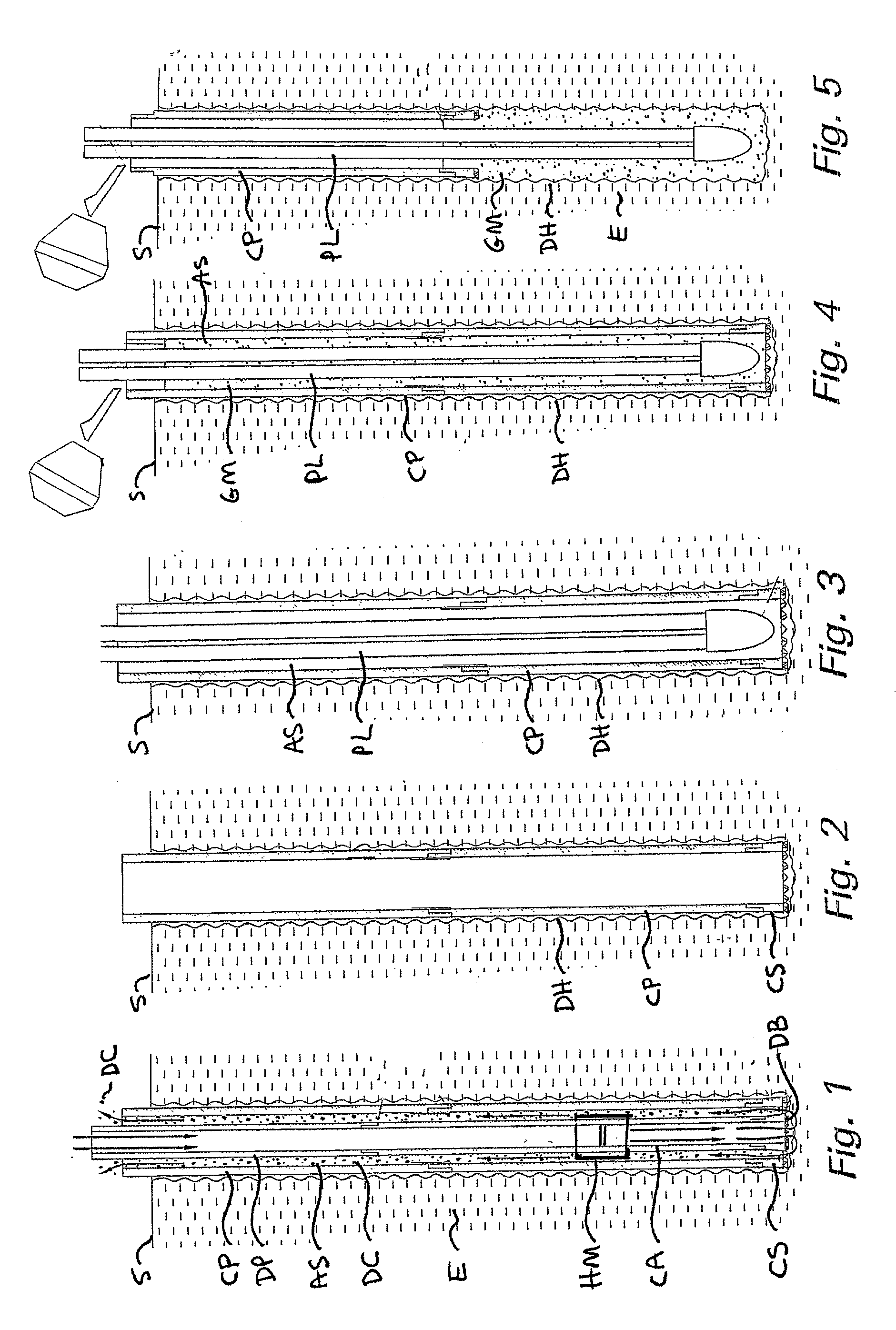
[0032] Five stages of a method according to the present invention, are illustrated in FIGS. 1-5.

[0033] In one dual pipe drilling method according to the present invention, a casing pipe CP is fitted with an open casing shoe as shown in FIG. 1. As the casing pipe CP is rotated and hammered, a plurality of cutters CT around the circumference of the drilling shoe DS remove material slightly thicker than the wall thickness of the following casing, allowing the casing to be advanced into the earth. Simultaneously, an inner drill pipe DP has a cutting bit member DB threadedly attached to the end of the drill pipe so that, when the inner drill pipe is rotated, remaining material inside of the casing pipe CP is removed, allowing the drill pipe DP and the casing pipe CP to be advanced through the earth E at the same rate. Compressed air CA is pumped down hole through the hollow drill pipe DP and out of the end of the drill bit DB, drill cuttings DC removed by the rotary (and hammering) actio...


PUM


Abstract

A method and system for drilling creating a wellbore which, in at least certain aspects, includes positioning a drilling apparatus at a desired location at the earth surface, the drilling apparatus having rotating and hammering apparatus for simultaneously rotating and hammering a dual tubular string into the earth, the dual tubular string with an outer casing string spaced apart by an annular space from an inner drill pipe string, both the outer casing and inner drill pipe string being hollow, a drill bit secured to a lowermost end of the inner drill pipe string and, optionally, a casing drill apparatus secured at a lowermost end of the casing string, drilling through the earth to form the wellbore by simultaneously rotating and hammering the dual tubular string with the drilling apparatus; and, in certain aspects, installing a geothermal heat loop and grouting the space around it.

Description

[0001] 1. Field of the Invention[0002] The present invention is directed to underground heat exchange systems; to apparatus and methods for drilling wellbores for such systems; and to installing such systems.[0003] 2. Description of Related Art[0004] Earth loop energy transfer systems are well known, as are methods for drilling boreholes into which such loops are installed and methods for installing the loops. In such systems, heat is exchanged with the earth using a closed loop pipe or series of closed loop pipes buried in the ground through which a heat transfer fluid is circulated. There is no direct contact of the fluid with the earth. An exchange of heat occurs if there is a difference between the temperature of the fluid circulating in the pipe and the earth temperature,--primarily by conduction through the wall of the earth loop. If a system is operating in a heating mode, heat is taken from the fluid inside of this circulating loop, e.g. by a heat exchanger in heat pump equi...

Claims


Application Information

Patent Timeline
Patent Type & Authority Applications(United States)
IPC IPC(8): E21B7/20E21B15/00E21B19/14F24J3/08
CPCE21B7/20E21B7/201E21B15/003Y02E10/125F24J3/083F24J2003/088E21B19/146F24T2010/53F24T10/15Y02E10/10
Inventor JOHNSON, HOWARD E. JR.
Owner ENLINK GEOENERGY SERVICES
Why Eureka
Try Eureka