Novel cable bridge cover plate

A technology of cable tray and cover plate, applied in electrical components and other directions, can solve the problems of not easy to disassemble, damage the cable tray, reduce the performance of the cable tray, etc., to achieve convenient and quick installation, improve the performance, avoid hard collision and over The effect of heavy loads

Inactive Publication Date: 2016-05-25
CHENGDU GERUISI CULTURAL COMM
View PDF11 Cites 4 Cited by
  • Summary
  • Abstract
  • Description
  • Claims
  • Application Information

AI Technical Summary

Problems solved by technology

For the existing cable trays, most of them include a bottom plate, side panels and cover plates, and the structure of the cover plate is often relatively simple, such as being directly snapped between the side panels of the cable tray, such a setting method is not easy to carry out Disassembly and assembly are laborious and labor-intensive. At the same time, when the cable tray is used in a harsh working environment, such as when there are often falling objects above the cable tray, the falling objects will not only impact the cover plate of the cable tray. , and when a large number of falling objects accumulate, the cover plate will be heavily loaded, and in severe cases, the cable tray will be damaged, thereby greatly reducing the performance of the cable tray

Method used


Image

  • Novel cable bridge cover plate

Examples


Embodiment Construction

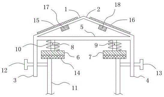
[0013] Such as figure 1 As shown, a new cable tray cover plate includes a plate body, and the plate body includes a left slant plate 1 and a right slant plate 2 fixedly connected to the right side of the left slant plate 1, and the left slant plate 1 is from left to right Extending obliquely upward, the right slant plate 2 extends obliquely downward from left to right, thereby effectively avoiding the accumulation of dropped objects on the plate body, and the left vertical plate 3 is connected vertically downward to the left side of the left slant plate 1 On the right side of the right inclined board 2, a right vertical board 4 is connected vertically downward, and at the same time, a horizontally extending front rod 5 is also connected between the top front end of the left vertical board 3 and the top front end of the right vertical board 4, Between the top rear end of the left vertical board 3 and the top rear end of the right vertical board 4 is also connected a horizontall...


PUM


Abstract

The invention relates to a novel cable bridge cover plate. The novel cable bridge cover plate comprises a plate body, wherein the plate body comprises a left inclined plate and a right inclined plate; a left vertical plate is connected with the left side of the left inclined plate, and a right vertical plate is connected with the right side of the right inclined plate; a front rod is connected between the front ends of the top parts of the left and right vertical plates, and a back rod is connected between the back ends of the top parts of the left and right vertical plates; a first front buffering plate and a second front buffering plate are arranged under the left and right ends of the front rod respectively; a first back buffering plate and a second back buffering plate are arranged under the left and right ends of the back rod respectively; a first front telescopic rod and a second front telescopic rod are connected between the first and second front buffering plates and the front rod; a first back telescopic rod and a second back telescopic rod are connected between the first and second back buffering plates and the back rod; helical springs are arranged on the exteriors of the telescopic rods separately in a sleeving manner; a left threaded through hole and a left locking screw rod are distributed on the left vertical plate; and a right threaded through hole and a right locking screw rod are distributed on the right vertical plate. By adoption of the structure, the novel cable bridge cover plate can be mounted conveniently and rapidly; and in addition, hard collision and overweight load of falling items can be effectively avoided.

Description

technical field [0001] The invention relates to a novel cable bridge cover plate. Background technique [0002] In the field of electric power construction, cable trays are often used for centralized placement of cables, which not only ensures the orderly placement of cables, but also ensures the safety of cables. For the existing cable trays, most of them include a bottom plate, side panels and cover plates, and the structure of the cover plate is often relatively simple, such as being directly snapped between the side panels of the cable tray, such a setting method is not easy to carry out Disassembly and assembly are laborious and labor-intensive. At the same time, when the cable tray is used in a harsh working environment, such as when there are often falling objects above the cable tray, the falling objects will not only impact the cover plate of the cable tray. , and when a large number of falling objects accumulate, the cover plate will be heavily loaded, and in seve...

Claims


Application Information

Patent Timeline
Patent Type & Authority Applications(China)
IPC IPC(8): H02G3/04
CPCH02G3/0418
Inventor 曾玥
Owner CHENGDU GERUISI CULTURAL COMM
Why Eureka
Try Eureka