
Method and encoder system for encoding video

An encoder and coding technology, applied in the field of encoder systems, can solve the problems of annoying coding artifacts in images, reduction of frame frequency of intra-frame coding, etc.

Active Publication Date: 2016-05-25
AXIS
View PDF5 Cites 5 Cited by
  • Summary
  • Abstract
  • Description
  • Claims
  • Application Information

AI Technical Summary

Problems solved by technology

However, because this implies that the frequency of intra-coded frames is reduced, errors caused by predictions employed when coding intra-coded frames can propagate further, leading to annoying coding artifacts in the displayed image

Method used


Image

  • Method and encoder system for encoding video
  • Method and encoder system for encoding video
  • Method and encoder system for encoding video

Examples


Embodiment Construction

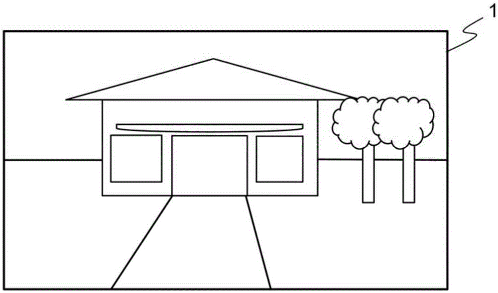
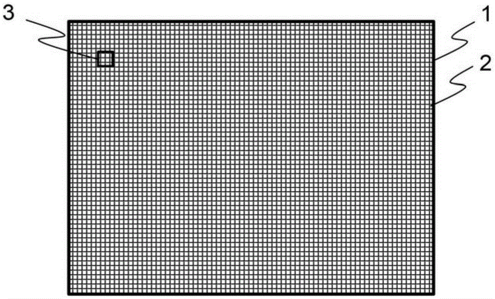
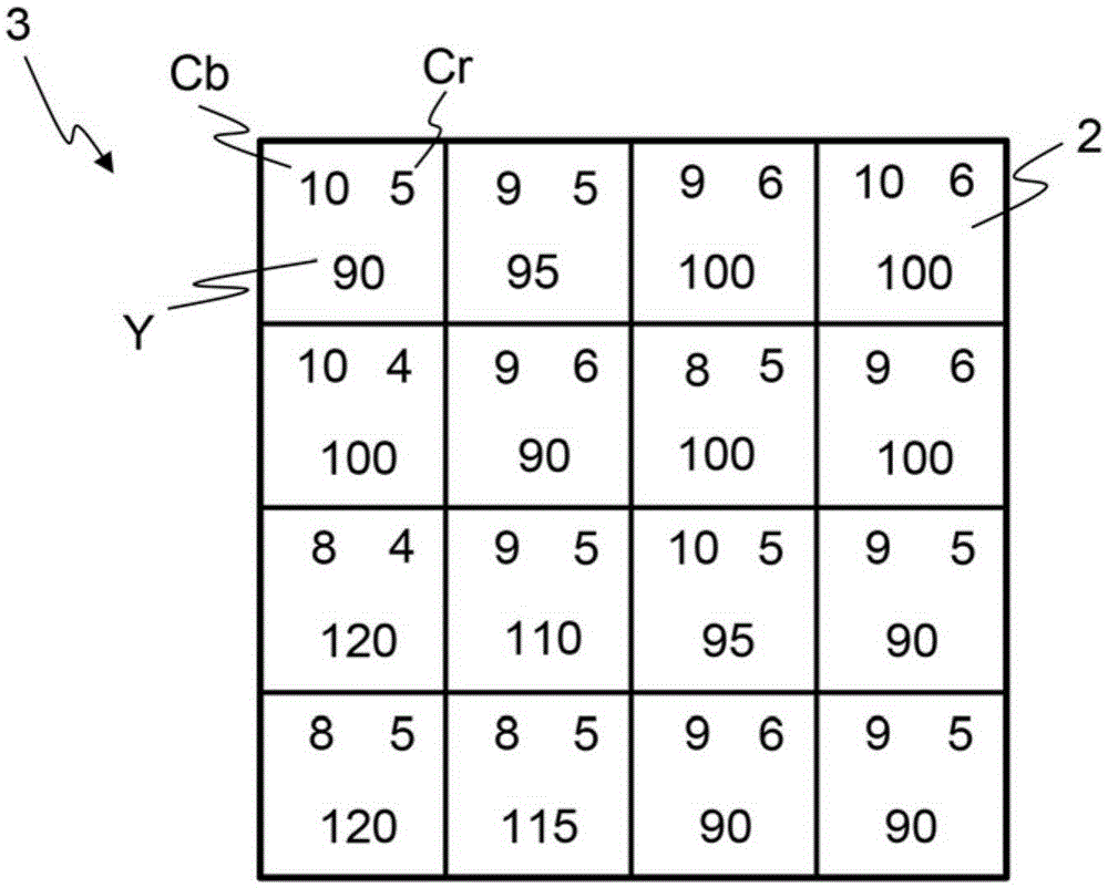
[0037] exist figure 1 A digital image 1 is shown in , which depicts the scene being monitored. Image 1 consists of a number of pixels 2, as in figure 2 The pixels shown in the figure. For example, image 1 may be 1280 pixels wide and 960 pixels high. The image 1 is represented in the YCbCr color space, which means that each pixel 2 has a luminance value Y, a chrominance blue value Cb and a chrominance red value Cr. exist image 3 , illustrated in Image 1 by figure 2 Box 3 schematically represents a small part. This small portion of image 1 is 4 pixels wide by 4 pixels high. for image 3 For each pixel in 2, the upper left number indicates the Cb value, the upper right number indicates the Cr value, and the bottom number indicates the Y value of that pixel.

[0038] The image 1 needs to be encoded when it is stored or transmitted eg to a control center where an operator or guard can observe the displayed image of the monitored scene. In this example, a codec working a...


PUM


Abstract

The invention discloses a method and encoder system for encoding video. The method comprises the steps of receiving (S02) information representative of pixels in a current digital image frame of a video to be encoded, calculating (S03) a group value for each group of neighboring pixels based on the received information, accumulating (S04) group values of corresponding groups of pixels in a first sequence of frames to form a first accumulation of accumulated group values, accumulating (S05) group values of corresponding groups of pixels in a second sequence of frames to form a second accumulation of accumulated group values, wherein the second sequence includes frames captured over a longer period of time than the first sequence, comparing (S06) accumulated group values of the first accumulation with accumulated group values of the second accumulation, calculating (S07) a global change value based on the comparison, setting (S08) a GOP length based on the global change value; and encoding (S09) the current image frame as an intra-frame or inter-frame based on the GOP length. An encoder system for encoding video is also disclosed.

Description

technical field [0001] The present invention relates to the field of digital image compression, in particular to a method for encoding video and an encoder system for encoding video. Background technique [0002] In digital video systems, such as in network camera surveillance systems, video sequences are compressed using various video encoding methods before transmission. In many digital video coding systems, two main modes are used to compress video frames in a sequence of video frames: intra mode and inter mode. In intra mode, the luma and chroma channels are encoded by exploiting the spatial redundancy of pixels within a particular channel of a single frame through prediction, transform, and entropy coding. A coded frame is called an intra-coded frame, and may also be called an 1-frame. In contrast, Inter-mode exploits temporal redundancy between separate frames and relies on motion-compensated prediction techniques that, for a selected block of pixels, vary by encodin...

Claims


Application Information

Patent Timeline
IPC IPC(8): H04N19/86H04N19/176H04N19/182H04N19/142H04N19/527
CPCH04N19/172H04N19/114H04N19/137H04N19/142H04N19/87H04N19/107H04N19/105H04N19/177H04N19/179H04N19/182H04N19/186H04N19/503H04N19/593
Inventor X·D·范维克托·埃德帕尔姆伏莱德瑞克·皮尔拉尔斯·佩尔松亚历山大·马丁斯
Owner AXIS
Learn More