Valve that can be electromagnetically actuated

An electromagnetic and valve seat technology, applied in the field of pressure regulating valves, can solve problems such as difficult pressure regulation and adverse effects on pressure regulation accuracy, and achieve low cost effects

Inactive Publication Date: 2016-05-25
ROBERT BOSCH GMBH
View PDF8 Cites 0 Cited by
  • Summary
  • Abstract
  • Description
  • Claims
  • Application Information

AI Technical Summary

Problems solved by technology

The disadvantage of this radial vibration is that it makes it difficult to regulate the pressure in pressure medium systems by electronic control of such valves
That is, radial vibrations adversely affect the pressure regulation accuracy of the valve

Method used


Image

  • Valve that can be electromagnetically actuated
  • Valve that can be electromagnetically actuated
  • Valve that can be electromagnetically actuated

Examples


Embodiment Construction

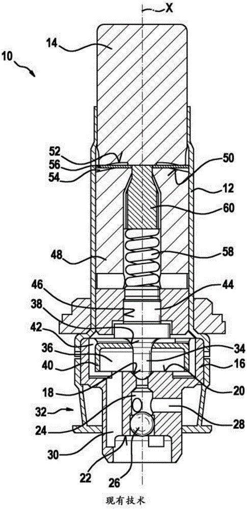
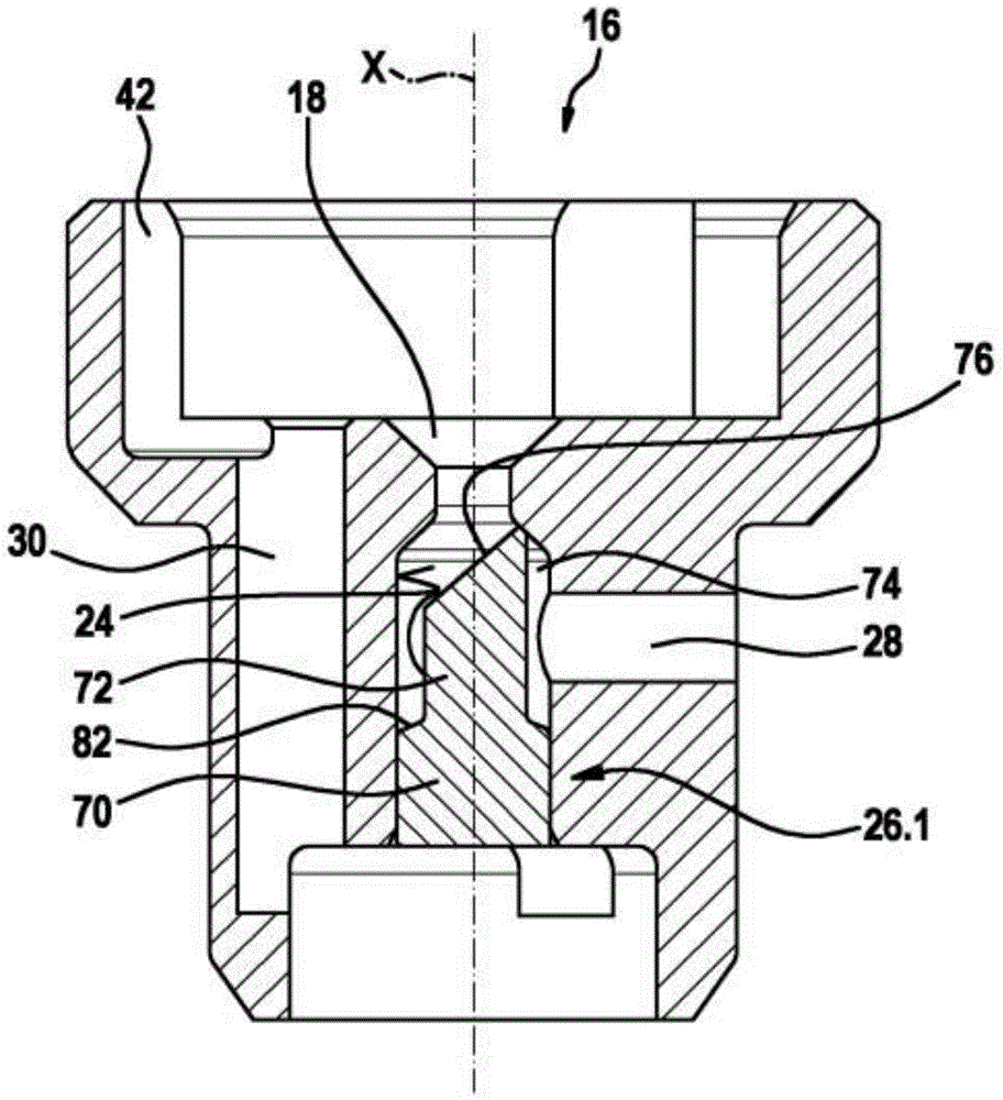
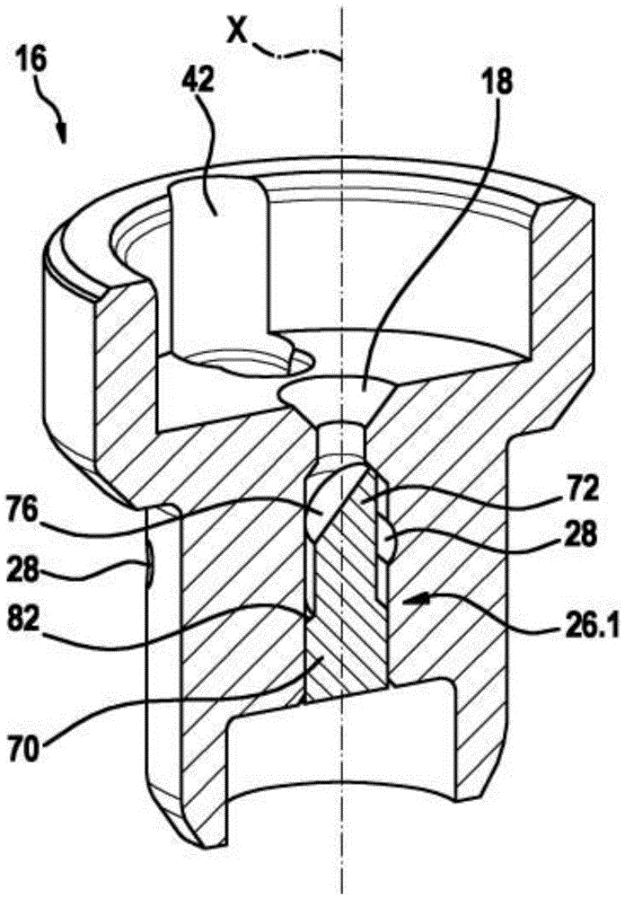
[0014] figure 1 The solenoid-operable valve 10 known from the prior art is shown in longitudinal section. The illustration of the solenoid coil that completes the valve 10 is intentionally omitted for clarity. The valve 10 has a sleeve-shaped valve housing 12 on which figure 1 A plug-like pole core 14 made of a magnetically conductive material is inserted into the open end of the middle upper part. The pole core 14 is fixedly connected to the valve housing 12. In the valve housing 12 figure 1 The open end of the middle and lower part is closed by a seat body 16 which is also fixedly connected to the valve housing 12. The seat body 16 forms a valve seat 18, which is arranged on the longitudinal axis X-X of the valve 10 and is formed at the base of the first flat depression 20 that is open toward the inside of the valve housing 12. The valve seat 18 itself is configured, for example, in the shape of a conical seat. Opposite the flat recessed portion 20 that is open to the insi...


PUM


Abstract

The invention relates to a valve that can be electromagnetically actuated, in particular a pressure control valve of a slip-controllable vehicle brake system. Known such valves (10) have a seat body (16). Said seat body comprises a valve seat (18), at least one inflow channel (28), and an outflow channel (30). In order to avoid a hydraulic short circuit between the inflow channel (28) and the outflow channel (30) when the valve seat (18) is closed, a shut-off element (26) is present. According to the invention, the shut-off element (26.1, 26.2) is equipped with flow-directing means (72.1, 72.2). Said flow-directing means (72.1, 72.2) prevent the partial flows from the inflow bores (28) from hitting each other and direct the flow to a closing body (34), which controls the valve seat (18), in such a way that a transverse force is applied to the closing body when the closing body performs a stroke motion. Said transverse force radially deflects the closing body (34) during an opening or closing motion and thus causes an effect that stabilizes the stroke motion and dampens radial vibrations. Because of said effect, the valve (10) has better pressure control properties.

Description

Technical field [0001] The present invention relates to an electromagnetically operated valve according to the features of the preamble of claim 1, in particular a pressure regulating valve of a vehicle brake device with anti-skid control. Such valves are known from DE102010002469A1 or DE102011079339A1 in terms of their structural design. The valve has a seat body, which in addition to constituting a valve seat also forms at least one inlet channel for guiding the pressure medium and an outlet channel for leading out the pressure medium. In order to avoid a hydraulic short circuit between these channels when the valve seat is closed, a blocking element is provided. In the cited prior art, a metal ball is used as a blocking element, and the metal ball is pressed into the vertical hole downstream of the inlet of the inflow channel in the vertical hole. Metal balls, for example, are used in large quantities for rolling bearings and are therefore particularly inexpensive in cost, ...

Claims


Application Information

Patent Timeline
IPC IPC(8): F16K31/06B60T8/36F16K1/42
CPCB60T8/363F16K31/0655F16K31/0665F16K1/12F16K1/36
Inventor P·戈德比隆E·库尔兹
Owner ROBERT BOSCH GMBH
Why Eureka
Try Eureka