Displacement control method and device for grasping workpiece by manipulator of injection molding machine

A technology of displacement control and manipulator, which is applied in the field of injection molding machine manipulator adjustment, can solve the problems of large volume and low work efficiency, and achieve the effect of increasing processing efficiency, reducing workload, and reducing the steps of adjusting the manipulator

Active Publication Date: 2017-08-25
郑州世纪精信机械制造有限公司
View PDF4 Cites 0 Cited by
  • Summary
  • Abstract
  • Description
  • Claims
  • Application Information

AI Technical Summary

Problems solved by technology

In the traditional technology, the staff needs to stand between the movable mold and the fixed mold, and gradually move the manipulator through the control handle, so as to move the manipulator to the position where it can successfully grab the product processed by the replaced mold. This process is very long. , it is necessary to repeatedly test whether the position of the manipulator holding device can correspond to the position on the mold where the workpiece can be grabbed, so the staff needs to keep pressing the relevant buttons on the control handle to control the manipulator to move accordingly. The efficiency is low, and the mold equipment of the injection molding equipment is generally large in size, and there is a greater risk for the staff to stand between the molds

Method used


Image

  • Displacement control method and device for grasping workpiece by manipulator of injection molding machine
  • Displacement control method and device for grasping workpiece by manipulator of injection molding machine
  • Displacement control method and device for grasping workpiece by manipulator of injection molding machine

Examples


Embodiment Construction

[0041] The following will clearly and completely describe the technical solutions in the embodiments of the present invention with reference to the accompanying drawings in the embodiments of the present invention. Obviously, the described embodiments are only some, not all, embodiments of the present invention. Based on the embodiments of the present invention, all other embodiments obtained by persons of ordinary skill in the art without making creative efforts belong to the protection scope of the present invention.

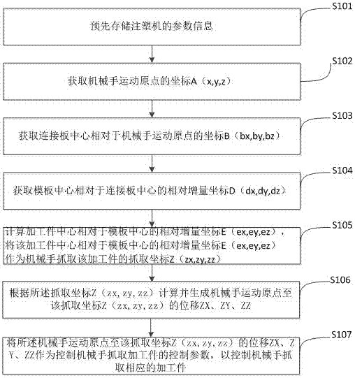
[0042] See figure 1 , figure 1 It is a flow chart of an embodiment of the displacement control method for the manipulator of the injection molding machine to grab the workpiece in the present invention. The displacement control method for the manipulator of the injection molding machine to grab the workpiece in this embodiment includes the following steps:

[0043] S101. Use a storage module to pre-store the parameter information of the injection molding mac...


PUM


Abstract

The invention discloses a displacement control method and device for grabbing a work-piece by a manipulator of an injection molding machine. The method comprises the steps of obtaining the coordinates of the movement origin of the manipulator; obtaining the coordinates of the center of a connection plate relative to the movement origin of the manipulator; obtaining the relative increment coordinates of the center of a template relative to the center of the connection plate through calculation according to the coordinates of the center of the connection plate; obtaining the relative increment coordinates E (ex, ey and ez) of the center of the work-piece relative to the center of the template through calculation according to the relative increment coordinates of the center of the template, and adopting the relative increment coordinates of the center of the work-piece relative to the center of the template as the grabbing coordinates Z (zx, zy and zz) of grabbing the work-piece by the manipulator, wherein E (ex, ey and ez) is equal to E (ex=0, ey=Mt+Mc-Tc-Sd and ez=0), Mt is the thickness of a fixed die of a die, Mc is the movement stroke of a movable die, Mh is the height of the highest point of the movable die relative to the die closing surface, Tc is the ejection stroke of an ejection pin of the die and Sd is the safe distance; generating the displacement from the movement origin of the manipulator to the grabbing coordinates Z (zx, zy and zz) through calculation according to the grabbing coordinates Z (zx, zy and zz).

Description

technical field [0001] The invention relates to the field of adjusting manipulators of injection molding machines, in particular to a displacement control method and device for manipulators of injection molding machines to grab workpieces. Background technique [0002] The injection molding machine mainly includes an injection mold and a manipulator. The injection mold is designed according to the shape of the workpiece to be processed. The injection mold includes a movable mold and a fixed mold. When the movable mold is opened, the manipulator takes out the processed workpiece from it. In order to enable the manipulator to take out the workpiece in each mold after replacement, it is necessary to adjust the gripping position of the manipulator (that is, the grabbing coordinates) again according to the position, shape, and size of the mold after each mold replacement. In the traditional technology, the staff needs to stand between the movable mold and the fixed mold, and grad...

Claims


Application Information

Patent Timeline
Patent Type & Authority Patents(China)
IPC IPC(8): B29C45/76B29C45/84
CPCB29C45/76B29C45/84B29C2945/76568
Inventor 田军李刚舒成燕陈华余朱启佳张杰
Owner 郑州世纪精信机械制造有限公司
Why Eureka
Try Eureka