Eureka AIR delivers breakthrough ideas for toughest innovation challenges, trusted by R&D personnel around the world.

an air jet loom

An air-jet loom and frame technology, which is applied in looms, textiles, textiles and paper making, etc., can solve the problem of low assembly accuracy of the main wallboard and the warp wallboard, affecting the service life of the beating shaft and the balance of the beating mechanism. It can save installation space, simple structure and heavy weight.

Active Publication Date: 2017-07-18
青岛东佳机械制造有限公司 +1
View PDF11 Cites 0 Cited by
  • Summary
  • Abstract
  • Description
  • Claims
  • Application Information

AI Technical Summary

Problems solved by technology

However, the above-mentioned air-jet loom has the following technical problems in practical application: (1) the above-mentioned wallboard generally adopts a split wallboard, that is, the main wallboard and the let-off wallboard are processed separately, and after the two are processed, they are connected by bolts and other parts. At the same time, this kind of wallboard has the following disadvantages in use: the assembly accuracy of the main wallboard and the let-off wallboard is not high, the vibration sound is loud when the air-jet loom is working, and the stability is poor; moreover, the air bag in the prior art It does not adopt an integral design with the main wallboard, and needs to be installed separately on the main wallboard, occupying a large space on the main wallboard; As a result, the balance of the beating-up mechanism is not good, and the vibration of the beating-up shaft is relatively large, which seriously affects the beating-up speed; although a kind of air-jet loom beating-up mechanism capable of balancing the weight above the beating-up shaft has been provided in the prior art , the beating-up mechanism also includes a plurality of counterweights arranged at intervals on the beating-up shaft, however, the above-mentioned counterweights will inevitably increase the bearing capacity of the beating-up shaft, which is not conducive to improving the beating speed on the one hand, and will affect the beating-up speed on the other hand. (3) The above-mentioned warp loosening mechanism adopts a positive warp loosening mechanism, and the positive warp loosening mechanism locks the eccentric sleeve on the warp loosening shaft, so that the back beam actively swings with the change of the opening, and sends it forward. Warp the warp or pull the warp backward so that the tension of the warp basically does not change; however, the eccentricity of the above-mentioned positive warp loosening mechanism is fixed and cannot meet the needs of different fabrics; in addition, the above-mentioned positive warp loosening mechanism is installed on a large wall (4) For the coiling and lifting mechanism in the above-mentioned coiling mechanism, when the bolting machine is performed, the usual practice is to use a crowbar to press the pre-coiling pressure roller and the coiling upper pressure roller first. The rollers are lifted up respectively, and the cloth of the bolt machine is passed around the coiling roller for a circle, and then the winding upper pressure roller and the coiling front pressure roller are respectively passed around, and then the coiling upper pressure roller and the coiling front pressure roller are lowered and pressed Cloth for the bolting machine, and finally the bolting cloth head is wound on the take-up roller to complete the bolting process; however, the above-mentioned bolting process is time-consuming, laborious, inefficient, and likely to have potential safety hazards in the operation process; (5) the above-mentioned cloth The edge mechanism usually adopts the pneumatic edge folding method, which uses the air flow to blow the yarn end into the shed, which has high efficiency and is easy to maintain. However, due to the influence of structure, air flow and other factors, the performance is unstable and the edge folding effect is not ideal.

Method used


Image

  • an air jet loom
  • an air jet loom
  • an air jet loom

Examples


Embodiment Construction

[0029] Below in conjunction with accompanying drawing and specific embodiment the present invention is described in further detail:

[0030] An air-jet loom comprises a frame, a warp let-off mechanism, a shedding mechanism, a weft insertion mechanism, a weft beating mechanism, a coiling mechanism, a warp loosening mechanism and a pneumatic folding mechanism; wherein, the frame includes a wallboard, a support and middle bracket.

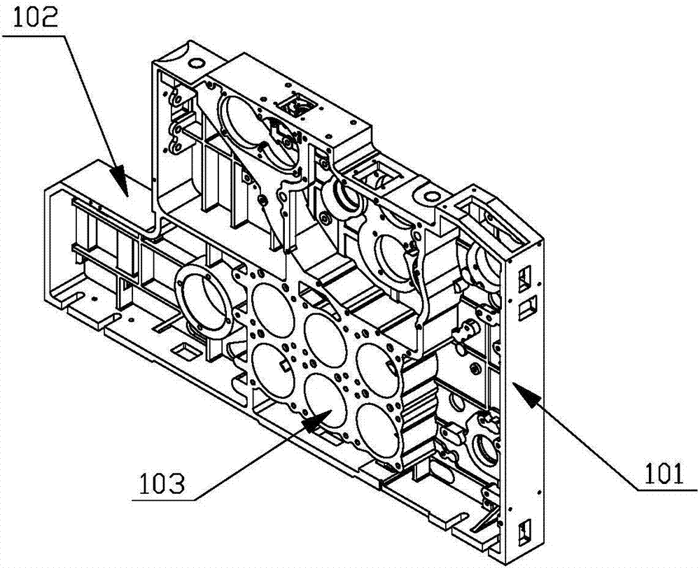
[0031] Such as figure 1 As shown, the wall panels include a main wall panel 101 and a let-off wall panel 102;

[0032] Through the above design, it is beneficial to ensure the integrity and stability of the air-jet loom wall panel, and saves the trouble of assembly.

[0033] Specifically, the main wallboard 101 and the warp let-off wallboard 102 are connected as a whole through a casting process, which is convenient for processing.

[0034] In addition, several air bag inner cavities 103 are provided on the main wall board 101 , the air bag inner c...


PUM


Abstract

The invention discloses an air-jet loom. The air-jet loom comprises a frame, a let-off mechanism, a shedding mechanism, a weft insertion mechanism, a beating-up mechanism, a winding mechanism, a warp loosening mechanism and a pneumatic tuck-in mechanism. The frame comprises wall plates, a supporting retainer and a middle support. By reasonable allocation of the wall plates, integrality of the air-jet loom can be improved beneficially; by reasonable allocation of the beating-up mechanism, balancing performance of the beating-up mechanism can be beneficially improved so as to increase beating-up speed of the beating-up mechanism; by reasonable allocation of the winding mechanism, an upper winding pressure roller and a lower winding pressure roller can be lift up at the same time; by reasonable allocation of the warp loosening mechanism, an eccentric adjusting block can slide along a horizontal side groove in an eccentric adjusting seat so as to change eccentricity, and warp loosening quantity can be adjusted according to different fabric requirements; by reasonable allocation of the pneumatic tuck-in mechanism, wefts can be smoothly guided into a stretch nozzle and accurately and stably fed into a cutter opening of the air-jet loom, and excellent tuck-in effects are achieved.

Description

technical field [0001] The present invention relates to an air jet loom. Background technique [0002] The air-jet loom includes a frame, a let-off mechanism, a shedding mechanism, a weft insertion mechanism, a weft beating mechanism, a take-up mechanism and other auxiliary mechanisms. Among them, the frame is composed of wall panels, braces and intermediate brackets, and other auxiliary mechanisms include warp loosening mechanisms, coiling and lifting mechanisms, and selvedge mechanisms. The general working principle of the air-jet loom is as follows: on the loom, the warp yarn exits from the warp beam, bypasses the back rest, passes through the warp dropper, heald eye and reed in turn to reach the weaving fell, and interweaves with the weft yarn injected by the airflow to form a fabric. The fabric bypasses the front beam, driven by the take-up roller, and then winds up on the cloth roller after passing through the guide roller; when the warp yarn and weft yarn interweave,...

Claims


Application Information

Patent Timeline
Patent Type & Authority Patents(China)
IPC IPC(8): D03D47/30D03D49/02D03D49/60D03D49/20D03D49/06
CPCD03D47/30D03D49/02D03D49/06D03D49/20D03D49/60
Inventor 王增福毕晨峰王凯丽许文科马维祥杨效慧单宝坤
Owner 青岛东佳机械制造有限公司
Why Eureka
Eureka Blog
Learn More