Oil pumping unit

A pumping unit and rotary connection technology, which is applied in the fields of production fluids, wellbore/well components, earth-moving drilling, etc., can solve the problems of low motor load rate and energy waste, and achieve the improvement of balance, load condition, and increase The effect of energy utilization

Inactive Publication Date: 2016-06-01
青岛讯达捷电子科技有限公司
View PDF0 Cites 1 Cited by
  • Summary
  • Abstract
  • Description
  • Claims
  • Application Information

AI Technical Summary

Problems solved by technology

The average load rate of the motor is only 20% to 30%, and the load rate of some motors is even lower, resulting in a great waste of energy

Method used


Image

  • Oil pumping unit
  • Oil pumping unit

Examples


Embodiment Construction

[0013] Below in conjunction with accompanying drawing and example the present invention will be further described:

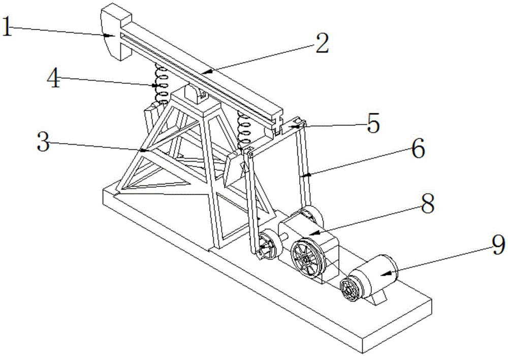
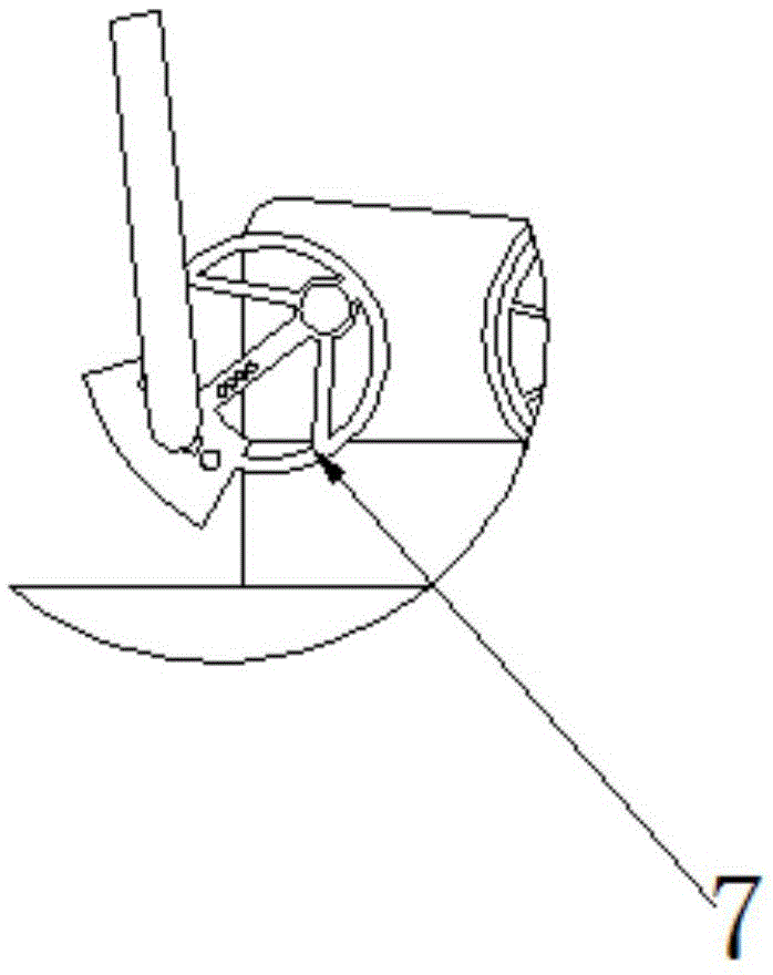
[0014] Such as figure 1 As shown, the pumping unit includes: a donkey head 1, a beam 2, a bracket 3, a high-pressure spring 4, a beam 5, a connecting rod 6, a crank 7, a reduction box 8 and an electric motor 9, and the donkey head 1 and one end of the beam 2 The solid connection integrally formed, the middle section of the traveling beam 2 is rotationally connected with the top of the bracket 3 through the rotating shaft, the other end of the traveling beam 2 is rotationally connected with the protrusion in the middle of the crossbeam 5 through the rotating shaft, and one end of the two high-pressure springs 4 is fixedly connected to the traveling beam. 2. One end of the beam is affixed, and the other end of the two high-pressure springs 4 is affixed to the other end of the beam 2 through a fixed connection, and the other ends of the two high-pressure springs 4 ...


PUM


Abstract

The invention relates to an oil pumping unit. The oil pumping unit comprises a horse head, a girder beam, a bracket, high-pressure springs, a cross beam, connecting rods, a crank, a reduction box and a motor. The horse head is fixedly connected with one end of the girder beam to be integrally formed. The middle section of the girder beam is rotationally connected with the top end of the bracket through a rotating shaft. The other end of the girder beam is rotationally connected with a middle protrusion of the cross beam through a rotating shaft. One end of one of the two high-pressure springs is fixedly connected with one end of the girder beam. The other high-pressure spring is fixedly connected with the other end of the girder beam. The other ends of the two high-pressure springs are fixedly connected with protrusions at the top ends of two long plates stretching out of the front side and the back side of the bracket correspondingly. According to the oil pumping unit, the energy utilization rate and production benefits are increased; the loading condition of suspension points can be improved, and the loading condition of the motor is relieved; the balance degree of the oil pumping unit is improved, and inverse torque is eliminated or weakened.

Description

technical field [0001] The invention relates to an oil pumping product, in particular to a pumping unit. Background technique [0002] At present, various manufacturers at home and abroad have successively developed pumping units such as front-mounted pumping units, out-of-phase crank pumping units, and air-balanced pumping units, which have overcome some shortcomings of conventional beam pumping units to varying degrees. But still can not get rid of the use of four-bar linkage to transform the rotary motion into linear reciprocating motion, resulting in the pumping unit balance effect has not been fundamentally improved, the acceleration is still high, the inertial load is large, and the total mass is doubled. Therefore, there is no It solves the fundamental problem, and makes the structure more complex, which increases a certain burden on repair, maintenance, and service life. [0003] At present, the pumping unit consumes a lot of electricity, and the work efficiency and...

Claims


Application Information

Patent Timeline
Patent Type & Authority Applications(China)
IPC IPC(8): E21B43/00
CPCE21B43/121
Inventor 李志华
Owner 青岛讯达捷电子科技有限公司
Why Eureka
Try Eureka