Non-pyrotechnic fusing connection separation device

A non-pyrotechnic technology for connecting and separating devices, applied in the aerospace field, can solve the problems of poor safety of the pyrotechnic device, polluted gas or debris, and high quality of the system structure, so as to improve the accuracy of fusing and unlocking, the device carrying capacity is large, and the structure compact effect

Pending Publication Date: 2020-01-21
SHENYANG AEROSPACE XINGUANG GRP
View PDF0 Cites 3 Cited by
  • Summary
  • Abstract
  • Description
  • Claims
  • Application Information

AI Technical Summary

Problems solved by technology

[0002] Most of the mechanisms involved in the connection and separation of weaponry and aerospace equipment use pyrotechnic devices as drives. The pyrotechnic devices have poor safety, relatively large impact loads during the working process, and the system has a large structural mass and cannot be repeatedly tested for performance. Insufficient in areas such as polluting gases or debris

Method used


Image

  • Non-pyrotechnic fusing connection separation device
  • Non-pyrotechnic fusing connection separation device
  • Non-pyrotechnic fusing connection separation device

Examples


Embodiment 1

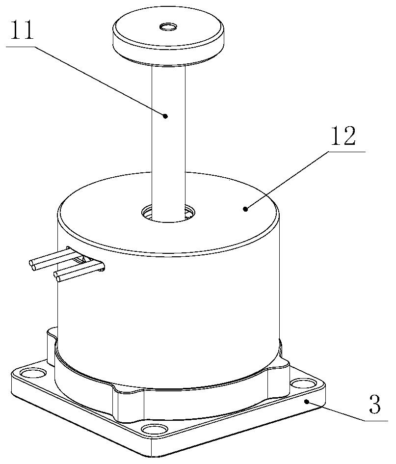
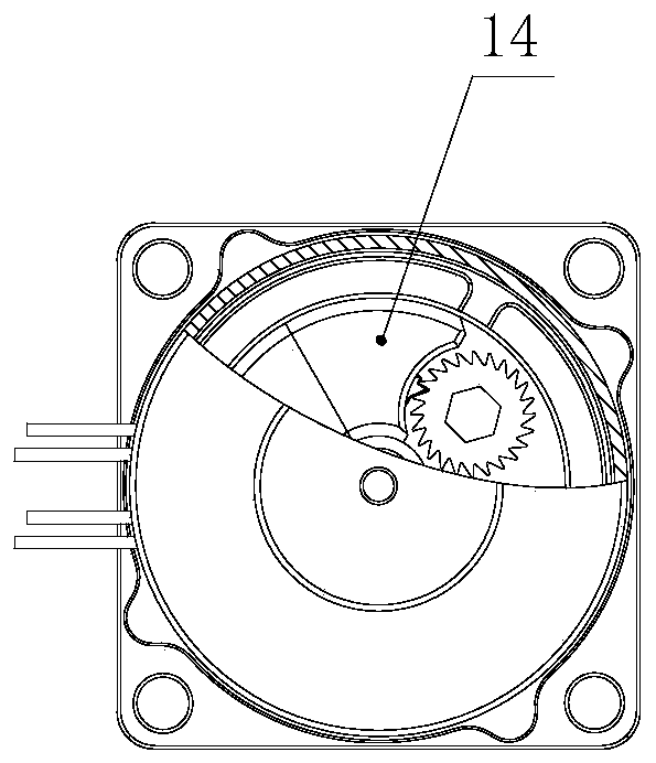
[0045] Such as Figure 1a , Figure 1b combine Figure 3a , Figure 3b , Figure 3c , Figure 6 , is a structural schematic diagram of a new non-pyrotechnic connection and separation device provided by an embodiment of the present invention, including a pressure rod 11, a housing I12, a connection seat 3, a split nut A14, a melting rope 4, a locking torsion spring 5, and a ratchet rope tightening mechanism 6. Insulating briquetting block a7, insulating briquetting block b8, fuse mechanism 9, separation spring 10, split nut A14 is installed on the connection seat 3, and the outer part of the split nut A14 set in the casing I12 is fixedly connected to the connection seat 3, and the casing I The upper surface of the upper surface is provided with a through hole, and one end of the pressure rod 11 is connected to the split nut A14 through the through hole of the shell I12, and the other end of the pressure rod 11 is connected to the base of the separation system. The split nut...

Embodiment 2

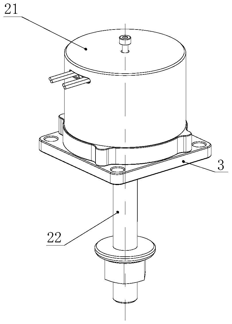
[0051] see Figure 2a , Figure 2b combine Figure 4a~Figure 4d As shown, it is a schematic structural diagram of a new non-pyrotechnic connection and separation device provided by another embodiment of the present invention. In this embodiment, the casing II21, pull rod 22, and split nut B24 are used to replace Figure 1a , Figure 1b Shell I12, pressure rod 11, split nut A14 in the middle, and a conical cap 23, top cap spring 25, anti-off bolt 26 are added, and further, the pull rod 22 passes through the connecting seat 3 to connect with the split nut B24, The rest of the structure remains unchanged. The specific structure is: the split nut B24 is installed on the connecting seat 3, the shell 21 is set on the outside of the split nut B and connected with the connecting seat, the lower surface of the connecting seat is provided with a through hole, and the pull rod 22 One end is connected to the split nut B through the through hole, the other end of the pull rod is connect...


PUM


Abstract

The invention relates to a non-pyrotechnic fusing connection separation device. The non-pyrotechnic fusing connection separation device is structurally characterized in that a valving nut A is mountedon a connection base, the shell I is sleeves the outer part of the split nut A and is connected with the connection base, and one end of a press rod is connected with the valving nut A; the valving nut A comprises a nut flap A I, a nut flap A II and a nut flap A III, wherein a ratchet wheel rope tightening mechanism is mounted in the nut flap A I, a fusing mechanism is mounted in the nut flap A II, a locking torsion spring and a fusing rope are sequentially wound around the outer part of the valving nut A, the fixing end of the locking torsion spring is fixedly mounted on the nut flap A III,the free end of the locking torsion spring is connected with one end of the fusing rope, and the other end of the fusing rope is connected with the ratchet wheel rope tightening mechanism. The non-pyrotechnic fusing connection separation device has the characteristics of small volume, light weight, large bearing capacity, energy conservation and environmental protection, and capable of repeatedlytesting and using.

Description

technical field [0001] The invention belongs to the field of aerospace, in particular to a novel non-pyrotechnic fusing connection separation device. Background technique [0002] Most of the mechanisms involved in the connection and separation of weaponry and aerospace equipment use pyrotechnic devices as drives. The pyrotechnic devices have poor safety, relatively large impact loads during the working process, and the system has a large structural mass and cannot be repeatedly tested for performance. Insufficient in areas such as polluting gases or debris. With the use of small satellites and high-precision micro-detection equipment, it is urgent to develop a new connection and separation mechanism with small size, light weight, large load, energy saving and environmental protection, low impact or even no impact, so as to adapt to the growing micro-weapon system and small-scale delivery. Rocket application requirements. Contents of the invention [0003] The technical ...

Claims


Application Information

Patent Timeline
Patent Type & Authority Applications(China)
IPC IPC(8): B64G1/64
CPCB64G1/645B64G1/646
Inventor 赵航关发财马国成叶耀坤丁锋王波
Owner SHENYANG AEROSPACE XINGUANG GRP
Why Eureka
Try Eureka