Pantograph offset detection method and system

A technology of offset detection and pantograph, which can be used in measurement devices, instruments, optical devices, etc., and can solve the problem of low detection efficiency.

Inactive Publication Date: 2016-06-01
CHENGDU TIEAN SCI & TECH
View PDF5 Cites 9 Cited by
  • Summary
  • Abstract
  • Description
  • Claims
  • Application Information

AI Technical Summary

Problems solved by technology

[0005] The purpose of the present invention is to provide a pantograph offset detection method, which can solve the problem of low detection efficiency

Method used


Image

  • Pantograph offset detection method and system

Examples


Embodiment Construction

[0024] The core of the present invention is to provide a pantograph offset detection method, which can automatically detect the pantograph offset; another core of the present invention is to provide a pantograph offset detection system.

[0025] In order to enable those skilled in the art to better understand the solution of the present invention, the present invention will be further described in detail below in conjunction with the accompanying drawings and specific embodiments.

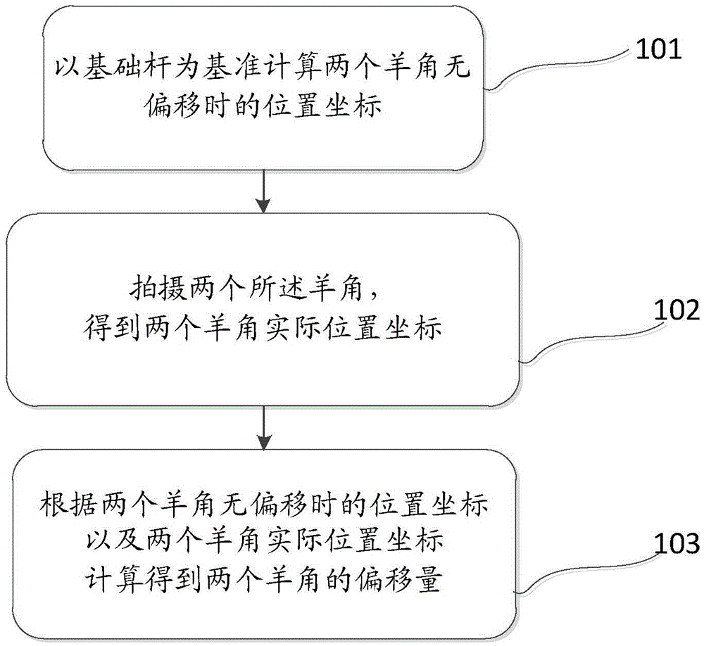
[0026] Please refer to figure 1 , figure 1 It is a flowchart of a pantograph offset detection method provided by an embodiment of the present invention.

[0027] The invention provides a pantograph offset detection method, comprising the following steps:

[0028] Step 101), taking the base pole as the reference to calculate the position coordinates of the two horns without offset;

[0029] Step 102), photographing the two horns to obtain the actual position coordinates of the two horns;

[0030...


PUM


Abstract

The invention discloses a pantograph offset detection method. The detection method comprises following steps of calculating position coordinates of two steering knuckles without offset by taking a basic rod as a reference; shooting the steering knuckles so as to obtain actual position coordinates of the steering knuckles; and according to the position coordinates of the steering knuckles without offset and the actual position coordinates of the steering knuckles, obtaining offsets of the steering knuckles. The invention also discloses a pantograph offset detection system. According to the invention, workers are prevented from going to a vehicle top to carry out operation, so automatic detection of offset of a pantograph central line is achieved; detection efficiency is increased; and labor cost is reduced.

Description

technical field [0001] The invention relates to the technical field of pantograph detection, in particular to a pantograph deviation detection method; in addition, the invention also relates to a pantograph deviation detection system. Background technique [0002] With the continuous development of my country's track construction, the market demand for various types of pantograph offset detection systems is increasing. [0003] We know that when the center line of the pantograph deviates more seriously, the pull-out value of the pantograph will often be too large, and there will be traffic failures such as bow pulling and netting during the running of the train, which will affect the safety of the train. [0004] The existing maintenance method is to use manual observation on the roof to judge the comprehensive state of the pantograph and the roof; if the pantograph is found to be seriously shifted, it is regarded as a sick bow and should be replaced and repaired accordingly...

Claims


Application Information

Patent Timeline
IPC IPC(8): G01B11/02
CPCG01B11/022
Inventor 王泽勇杨凯彭朝勇赵全轲高晓蓉张渝彭建平马莉向波谢任涛戴立新
Owner CHENGDU TIEAN SCI & TECH
Why Eureka
Try Eureka