Engine high pressure turbine clearance value correction method

A high-pressure turbine and engine technology, applied in measuring devices, instruments, etc., can solve problems such as differences in real results, amplifying rotor deviation, etc., and achieve the effects of improving precision and accuracy, controlling blade tip clearance, and reasonable blade tip clearance

Active Publication Date: 2016-06-01
AECC SHENYANG ENGINE RES INST
View PDF4 Cites 8 Cited by
  • Summary
  • Abstract
  • Description
  • Claims
  • Application Information

AI Technical Summary

Problems solved by technology
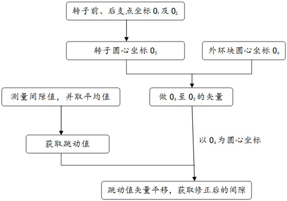
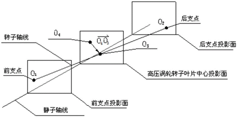
[0003] At present, the analysis method for the turbine clearance of the aero-engine is: respectively measure the diameter of the outer ring block of the high-pressure turbine of the aero-engine and the diameter of the tip of the rotor blade and calculate the corresponding average value, and use the average value difference between

Method used


Image

  • Engine high pressure turbine clearance value correction method
  • Engine high pressure turbine clearance value correction method
  • Engine high pressure turbine clearance value correction method

Examples


Embodiment Construction

[0027] In order to make the objectives, technical solutions and advantages of the present invention clearer, the technical solutions in the embodiments of the present invention will be described in more detail below in conjunction with the drawings in the embodiments of the present invention. In the drawings, the same or similar reference numerals denote the same or similar elements or elements having the same or similar functions throughout. The described embodiments are some, but not all, embodiments of the invention. The embodiments described below by referring to the figures are exemplary and are intended to explain the present invention and should not be construed as limiting the present invention. Based on the embodiments of the present invention, all other embodiments obtained by persons of ordinary skill in the art without creative efforts fall within the protection scope of the present invention. Embodiments of the present invention will be described in detail below ...


PUM


Abstract

The invention discloses an engine high pressure turbine clearance value correction method, and belongs to the technical field of aero-engine high pressure turbine clearance measurement analysis. Firstly the coordinates of center of circle O1 and O2 of the front and rear pivots of an engine high pressure turbine rotor on the same axial projection surface are acquired so that the coordinates of center of circle O3 of an axial blade center are determined; and then the coordinates of center of circle O4 of a high pressure turbine external ring block are acquired, circumferential distribution of all the external ring block jump values relative to the coordinates of center of circle O4 is drawn, and finally vector translation is performed on the circumferentially distributed external ring block jump values relative to the coordinates of center of circle O4 through a space vector O4O3<rightarrow> so that corrected engine high pressure turbine clearance value distribution is acquired. Association analysis of the rotor and stator diameter is performed according to the proportional position of the center of the high pressure turbine rotor between the pivots of the high pressure rotor and the relative position vector of the center and the high pressure turbine external ring center in the space so that the calculation result is more accurate and the circumferential distribution situation of the engine turbine clearance can be visually reflected.

Description

technical field [0001] The invention belongs to the technical field of measurement and analysis of high-pressure turbine gaps of aero-engines, and in particular relates to a correction method for gap values ​​of high-pressure turbines of engines. Background technique [0002] The engine turbine clearance refers to the distance between the tip of the engine turbine blade and the adjacent outer ring block. Due to the perennial operation of the engine, the gap value between the two will change. In the case of rapid acceleration and deceleration of the engine In order to improve the performance and reliability of modern aero-engines, many research institutions at home and abroad have carried out research on the control technology of the tip clearance, and the numerical analysis of the tip clearance is one of them. One of the important content. [0003] At present, the analysis method for the turbine clearance of the aero-engine is: respectively measure the diameter of the outer...

Claims


Application Information

Patent Timeline
IPC IPC(8): G01B21/16
CPCG01B21/16
Inventor 刘永泉赵翀梁海涛付鹏哲杨乐
Owner AECC SHENYANG ENGINE RES INST
Why Eureka
Try Eureka