
Optical detection apparatus

A technology of optical detection and equipment, applied in the field of optical detection, can solve problems such as limited operating table area, reduced operating space, dimness, etc., to achieve the effect of saving the area on the operating table and increasing stability

Inactive Publication Date: 2016-06-01
TIANJIN MINNING ELECTRONICS
View PDF0 Cites 0 Cited by
  • Summary
  • Abstract
  • Description
  • Claims
  • Application Information

AI Technical Summary

Problems solved by technology

[0002] In the process of circuit board production, the solder joints on the soldered circuit board need to be inspected. Because the solder joints are too small, the human eye cannot see clearly on a single screen. It is necessary to use an amplification device to complete the inspection. Since the circuit board is uneven Uneven, local light is too dim, when it is necessary to observe with magnifying equipment, it must be illuminated at the same time, so as to complete the detection of solder joints on the circuit board; this requires a detection equipment that can illuminate and amplify, so as to meet The need for circuit board inspection; the circuit board inspection is carried out on the operating table, but the area of ​​the operating table is limited. Fixing the testing equipment on the operating table will reduce the operating space and make the workers appear crowded when inspecting the circuit board.

Method used


Image

  • Optical detection apparatus
  • Optical detection apparatus
  • Optical detection apparatus

Examples


Embodiment Construction

[0023] Specific embodiments of the present invention will be described in detail below in conjunction with the accompanying drawings.

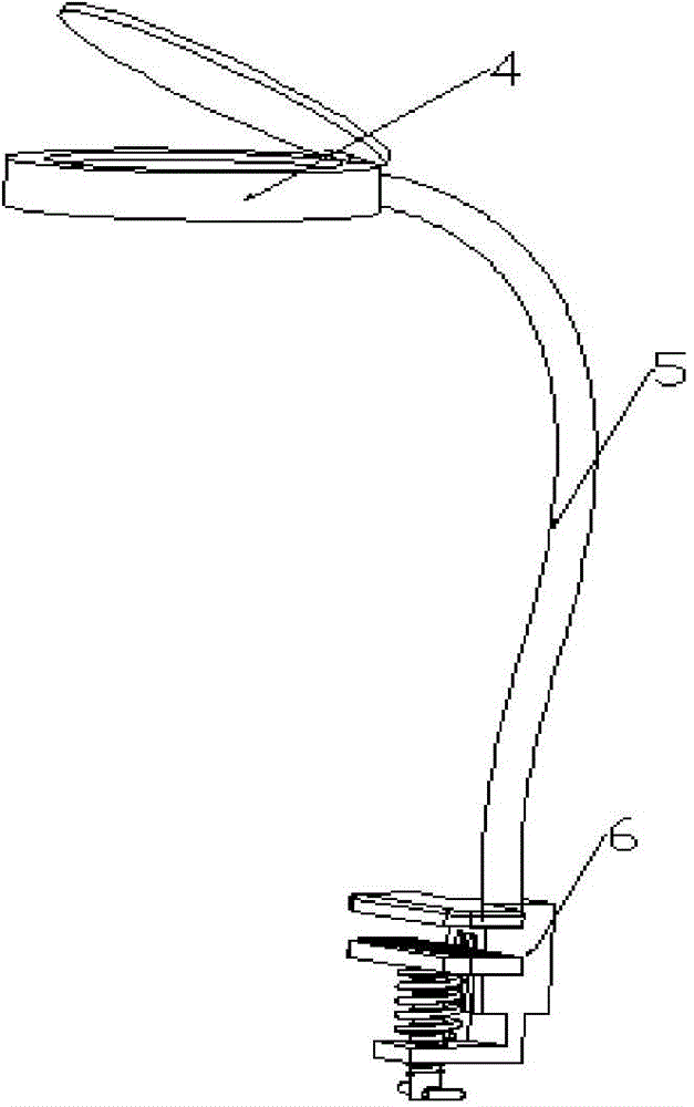
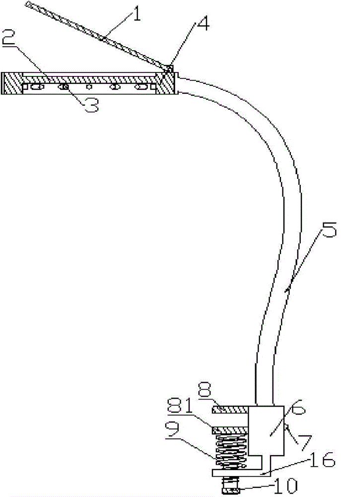
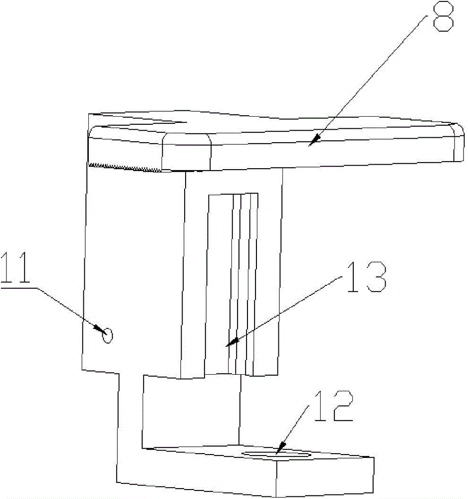
[0024] Such as figure 1 , figure 2 , image 3 , Figure 4 As shown, an optical detection device includes a magnifying glass main body 4, a shaping hose 5 and a fixed body 6, the magnifying glass main body 4 is provided with a magnifying glass 2, the magnifying glass main body 4 is connected with a shaping hose 5, and the shaping hose 5 is connected to the fixing body 6 The upper end of the fixed main body 6 is provided with a fixed upper plate 8, and the lower end of the fixed upper plate 8 is provided with a cross slide 13, and the cross slide 13 is provided with a fixed lower plate 81, and the lower end of the fixed main body 6 is provided with a fixed plate 16, and on the fixed plate 16 A fixing hole 12 is provided, and a fastening bolt 10 is worn on the fixing hole 12, and the fastening bolt 10 is pushed against the lower end of the fi...


PUM


Abstract

The present invention provides an optical detection apparatus comprising a magnifying glass body, a shaping soft tube and a fixing body, the magnifying glass body is provided with magnifying glass, the magnifying glass body is connected with the shaping soft tube, the shaping soft tube is connected with the fixing body, the upper end of the fixing body is provided with a fixing upper plate, the lower end of the fixing upper plate is provided with a cross-shaped slide way, the cross-shaped slide way is internally provided with a fixing lower plate, the lower end of the fixing body is provided with a fixing plate, the fixing plate is provided with a fixing hole, a fastening bolt penetrates the fixing hole, the fastening bolt props the lower end of the fixing lower plate, a spring is arranged between the fixing lower plate and the fixing plate, and the spring sleeves the fastening bolt. The optical detection apparatus can be used for high-quality detection of solder joints on a circuit board, meanwhile the optical detection apparatus can be fixed at the edge of a control console, the area of the control console is saved, and by additional arrangement of the spring is arranged between the fixing lower plate and the fixing plate, stability of the fastening bolt is increased, and the fastening bolt may not be loosen.

Description

technical field [0001] The invention relates to the field of optical detection, in particular to an optical detection device. Background technique [0002] In the process of circuit board production, the solder joints on the soldered circuit board need to be inspected. Because the solder joints are too small, the single-screen human eye cannot see clearly. It is necessary to use the amplification equipment to complete the inspection. Since the circuit board is uneven Uneven, the local light is too dim, when it is necessary to observe with amplifying equipment, it must be illuminated at the same time, so as to complete the detection of solder joints on the circuit board; in this way, a detection equipment that can illuminate and amplify is needed to meet The need for circuit board inspection; the circuit board inspection is carried out on the operation table, but the area of ​​the operation table is limited. Fixing the testing equipment on the operation table will reduce the ...

Claims


Application Information

Patent Timeline
IPC IPC(8): G01N21/00G01N21/88
Inventor 胡志有
Owner TIANJIN MINNING ELECTRONICS
Learn More