Icing photoelectric sensor and icing measuring device

A photoelectric sensor and photoelectric receiving tube technology, applied in the field of photoelectric sensors, can solve the problems of large thickness of ice coating on transmission lines, increased volume of icing sensors, small measurement range, etc., and achieves the effect of realizing large-scale icing detection.

Inactive Publication Date: 2016-06-01
HUAZHONG UNIV OF SCI & TECH +2
View PDF9 Cites 6 Cited by
  • Summary
  • Abstract
  • Description
  • Claims
  • Application Information

AI Technical Summary

Problems solved by technology

At present, icing sensors are used to detect the icing of transmission lines to monitor the icing of transmission lines, but the range of icing thickness of transmission lines that can be measured is relatively small, usually the maximum can only be measured at about 2mm, and usually in areas with harsh conditions such as border areas, transmission lines The line is covered with thick ice, and the existing icing sensors cannot meet the demand
The structure of the icing sensor in the prior art is usually that the outer surface of the infrared emitting tube is provided with photoelectric receiving tubes layer by layer, which usually results in a small measurement range for the ice thickness on the end face of the icing sensor. If the measurement range is increased, the photoelectric The increase in the distance between the receiving tube and the infrared emitting tube will lead to an increase in the volume of the icing sensor

Method used


Image

  • Icing photoelectric sensor and icing measuring device
  • Icing photoelectric sensor and icing measuring device

Examples


Embodiment Construction

[0025] The following will clearly and completely describe the technical solutions in the embodiments of the present invention with reference to the accompanying drawings in the embodiments of the present invention. Obviously, the described embodiments are only some, not all, embodiments of the present invention. Based on the embodiments of the present invention, all other embodiments obtained by persons of ordinary skill in the art without making creative efforts belong to the protection scope of the present invention.

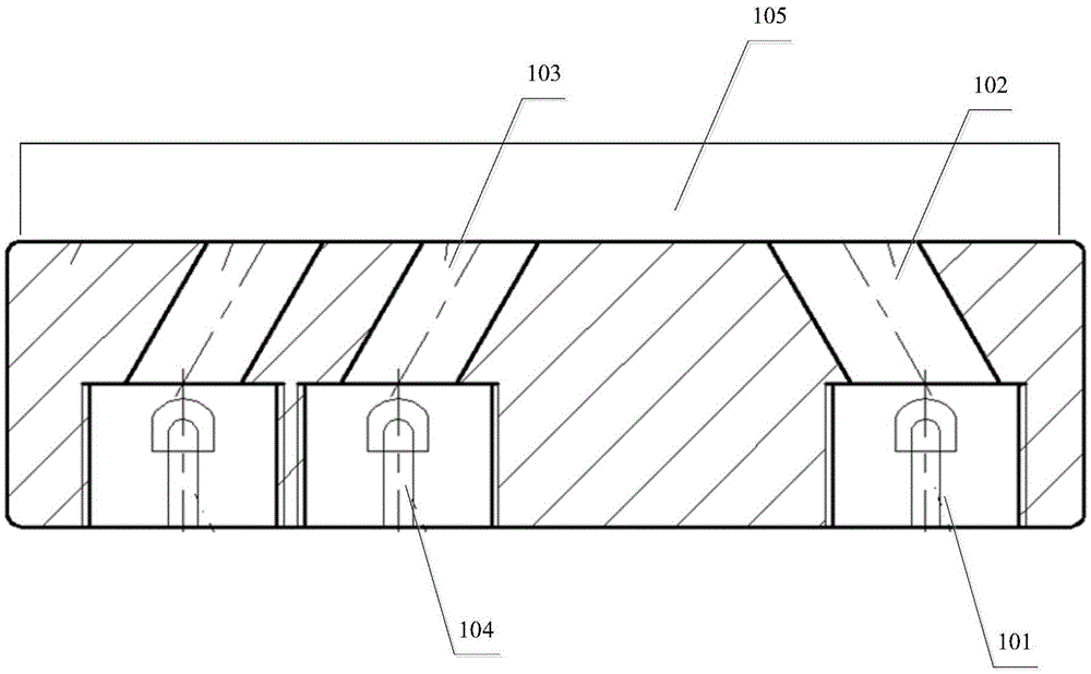
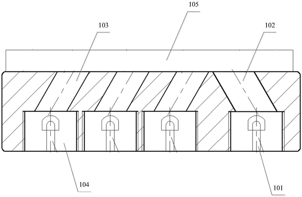
[0026] see figure 1 , figure 1 It is a schematic diagram of an icing photoelectric sensor provided by an embodiment of the present invention.

[0027] In a specific embodiment, a photoelectric sensor for icing is provided, including: the infrared emitting tube 101 for emitting infrared rays; The transmitting conduit 102; at least one photoelectric receiving tube 104 for receiving reflected rays reflected by the ice layer 105; the receiving conduit 103 for tr...


PUM


Abstract

The invention discloses an icing photoelectric sensor and an icing measuring device. The icing photoelectric sensor comprises an infrared emitting tube for emitting infrared rays, an emitting guide tube for transmitting the infrared rays from the infrared emitting tube to an ice layer, at least one photoelectric receiving tube for receiving reflection rays reflected by the ice layer, and a receiving guide tube for transmitting the reflection rays to the photoelectric receiving tube, a preset distance is formed between the photoelectric receiving tubes, and the infrared emitting tube, and the receiving guide tube and the emitting guide tube incline relative to the ice layer of a shell and form a preset angle. Small size of the icing photoelectric sensor is guaranteed while measuring range of ice covering thickness is widened obviously.

Description

technical field [0001] The invention relates to the technical field of photoelectric sensors, in particular to an icing photoelectric sensor and an icing measuring device. Background technique [0002] my country is one of the countries with serious icing on transmission lines in the world. The probability of accidents caused by icing on lines ranks among the top in the world, causing huge economic losses to the country and the people. Icing monitoring technology is to use various types of sensors to realize the judgment of icing by sensing the changes of physical, mechanical and optical properties after the surface of the object freezes. At present, icing sensors are used to detect the icing of transmission lines to monitor the icing of transmission lines, but the range of icing thickness of transmission lines that can be measured is relatively small, usually the maximum can only be measured at about 2mm, and usually in areas with harsh conditions such as border areas, tran...

Claims


Application Information

Patent Timeline
Patent Type & Authority Applications(China)
IPC IPC(8): G01N21/55
CPCG01N21/55
Inventor 葛俊锋杨先进闫泽豪叶林苏良智刘家齐刘伟浩黄中华方炯费敏高昱峰齐辉
Owner HUAZHONG UNIV OF SCI & TECH
Why Eureka
Try Eureka