
Shift lever device for vehicle

a technology of shifting lever and shift lever, which is applied in the direction of mechanical control devices, manual control with single controlling member, instruments, etc., can solve the problems of difficult installation of the shift lever, inability to maintain the configuration with high accuracy, etc., and achieves the effect of easy assembling operation, increased rigidity of the base, and easy change of the range position

Active Publication Date: 2006-09-28
FUJI KIKO CO LTD
View PDF4 Cites 4 Cited by
  • Summary
  • Abstract
  • Description
  • Claims
  • Application Information

AI Technical Summary

Benefits of technology

[0012] In common with the above-mentioned related arts, since the opening is enlarged so as to allow the rotation of the shift lever in attaching, rigidity of the whole base is reduced that much.
[0014] Installation of the shift lever is difficult because of a large range of operation needed for installation. In order to solve the above-mentioned problems in the related arts, an object of the present invention is to provide a shift lever device having a base that does not require a large opening, exhibits sufficient rigidity to prevent occurrences of warpage, enables reservation of dimensional accuracy and allows a shift lever to be assembled with ease.
[0016] According to the above aspect of the invention, by inserting the pivot shaft of the shift lever into the bearing holes through the guide grooves and fitting the bearing bushes to the bearing holes, the pivot shaft is rotatably supported by the bearing bushes rotatably. Consequently, it is possible to support the shift lever on the base rotatably, allowing the range position to be changed by the shift lever.
[0017] In the structure, since the bearing bushes are fitted to the bearing holes having the pivot shaft inserted through the guide grooves, the pivot shaft is prevented from falling away the bearing holes, allowing the shift lever to be rotatably supported by the bearing parts. Therefore, since there is no need to assemble the shift lever in its inclined condition, it eliminates the need for a large opening for inclining the shift lever to the base. Consequently, it is possible to increase rigidity of the base and also possible to make sure of appropriate dimensional accuracy with no possibility of an occurrence of warpage. Since the shift lever with no inclination is assembled into the base, the assembling operation can be accomplished with ease.
[0022] Then, since the positioning mechanism operates to make the axial center of the pivot shaft coincide with the center of the bearing hole, if only inserting the pivot shaft into the bearing hole, then it becomes possible to arrange the pivot shaft in position in the bearing hole. Thus, the pivot shaft can be fitted in the bearing part with ease and high accuracy.
[0024] In this case, since the positioning step is formed on the outer circumferential surface of the pivot shaft or formed on the base spart opposing the pivot shaft, it is possible to provide the positioning mechanism in either the pivot shaft or the base easily.

Problems solved by technology

However, there are the following problems in the above-mentioned related arts.
As a result, due to occurrence of such warpage, it is impossible to maintain its configuration with high accuracy.
Installation of the shift lever is difficult because of a large range of operation needed for installation.

Method used


Image

  • Shift lever device for vehicle
  • Shift lever device for vehicle
  • Shift lever device for vehicle

Examples


first embodiment

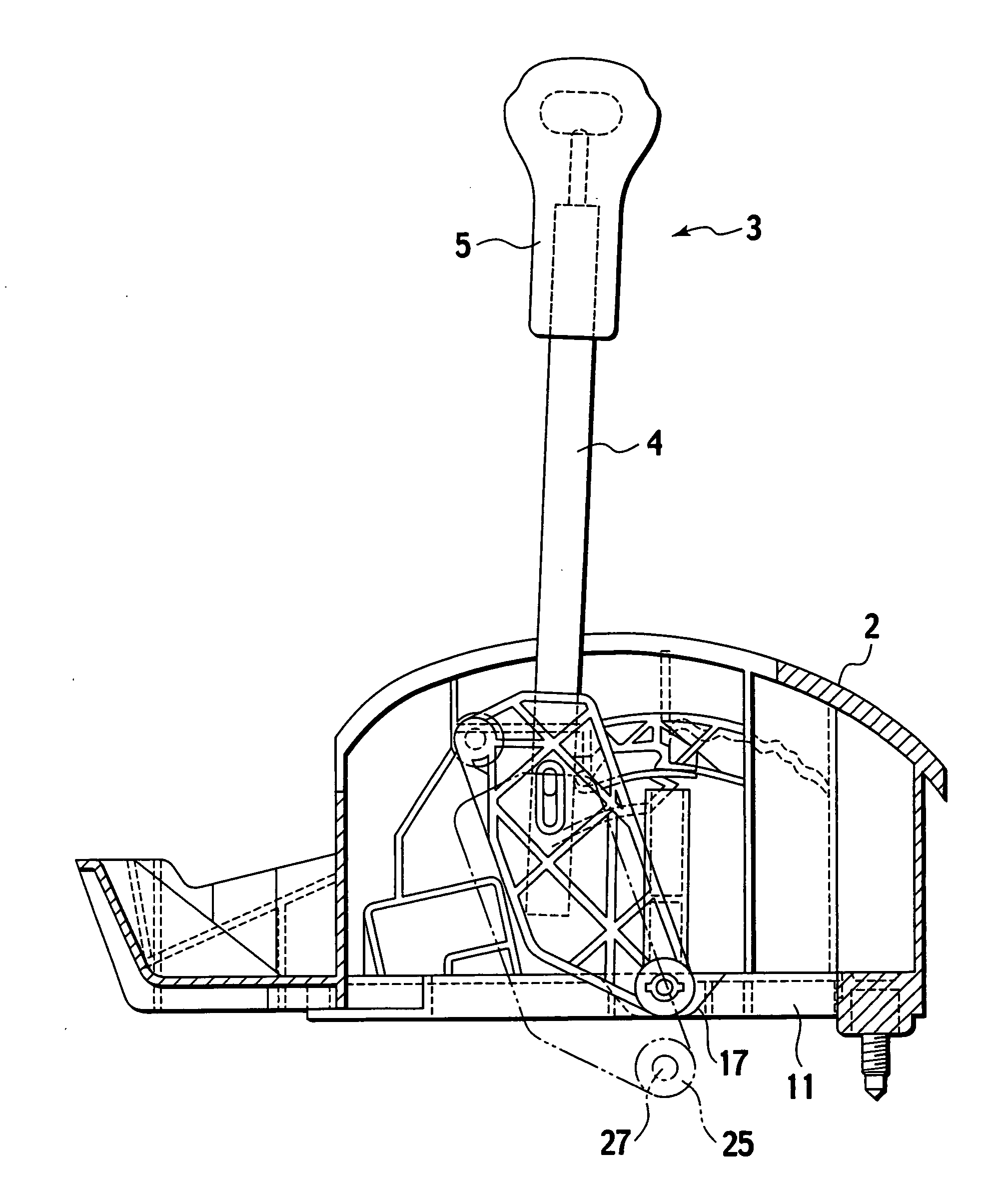
[0046] there are provided a pair of bearing bushes 33, 33 for holding the pivot shafts 27, 27. The bearing bushes 33, 33 are made of resinous material and also shaped to be substantially cylindrical. On condition that the pivot shafts 27, 27 are inserted into the bearing holes 29, 29 respectively, the bearing bushes 33, 33 are inserted into the bearing holes 29, 29 from the outside. Owing to the insertion, each of the bearing bushes 33 is interposed between the pivot shaft 27 and the bearing hole 29 to play a role of bearing the pivot shaft 27.

[0047] Each bearing bush 33 has a latch hook 35 and a pair of locking projections 37, 37 (as an anti-rotation mechanism) formed on the outer circumferential surface. In operation, when the latch hook 35 engages in the guide groove 31 as shown in FIG. 5, an engagement of the bearing bush 33 with the base 2 is accomplished. Thus, the latch hook 35 serves to prevent the bearing bush 33 from falling away the base 2.

[0048] On the outer circumfere...

2nd embodiment

2nd Embodiment

[0052] Next, the second embodiment of the present invention will be described in detail. FIG. 8 is an enlarged perspective view of a substantial part of a shift lever. In the second embodiment, elements identical to those of the first embodiment are indicated with the same reference numerals respectively. In the first embodiment, the present invention is applied to the shift lever device where the shift lever 3 is pivotally supported so as to allow a selecting of respective operating ranges arranged along a fore-and-aft direction of the vehicle body: “P” (parking range) position; “R” (reverse range) position; “N” (neutral range) position; “D” (drive range) position; “2” (second range) position; and “L” (low range) position. While, a shift lever 9 is accordance with the second embodiment is applied to a shift lever device capable of swinging in both fore-and-aft and left-and-right directions of a vehicle, for example, a so-called “gate-type” shift lever device where the...

second embodiment

[0053] the invention relates to the shift lever device with a manual mode. The shift lever 9 includes a select lever 61 and a crosswise shift lever 51. Being carried by the base 2, the select lever 61 is capable of swinging in the fore-and-aft direction of the vehicle body, about a lengthwise pivot shaft 63 as fulcrum. While, the crosswise select lever 51 is carried by the select lever 61 and capable of swinging in the left-and-right direction of the vehicle body, about a crosswise pivot shaft 74 as fulcrum. If a driver (or operator) manipulates the above operating part in the fore-and-aft direction of the vehicle body, then the crosswise shift lever 51 swings in integral with the select lever 61. While, if the driver manipulates the rod part 22 in the left-and-right direction of the vehicle body, only the crosswise shift lever 51 swings. In this way, by manipulating the rod part 22 in both fore-and-aft direction and left-and-right direction of the vehicle body in combination, an op...


PUM


Abstract

A shift lever device includes a shift lever having a pivot shaft formed at a base end of the shift lever integrally and a base having an opening formed to allow the shift lever to be inserted into the base and a pair of bearing parts formed so as to lie on opposing sides of the opening. The pivot shaft extends along a direction intersecting with a longitudinal direction of the shift lever. Each of the bearing parts has a bearing hole formed in the bearing part to adjoin the opening, a guide groove formed in the bearing part to communicate with the bearing hole, for introducing the pivot shaft into the bearing hole and a bearing bush which is to be inserted between the pivot shaft and the bearing hole. The bearing bush has a latch hook provided to engage with an interior of the bearing hole. The bearing bush is fitted to the bearing hole on condition that the pivot shaft is being inserting into the bearing hole through the guide groove, so that the shift lever is rotatably supported by the base through the bearing bush.

Description

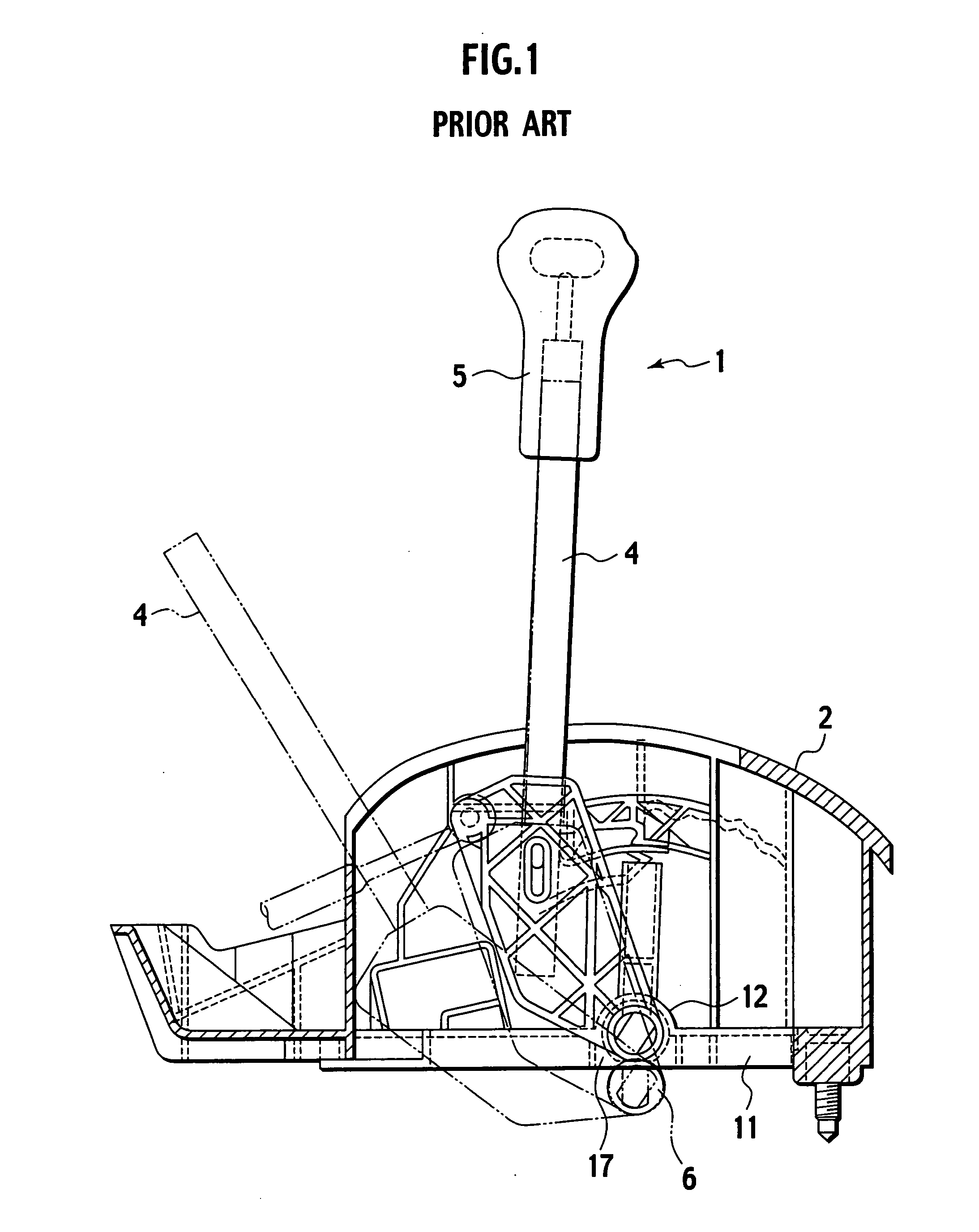
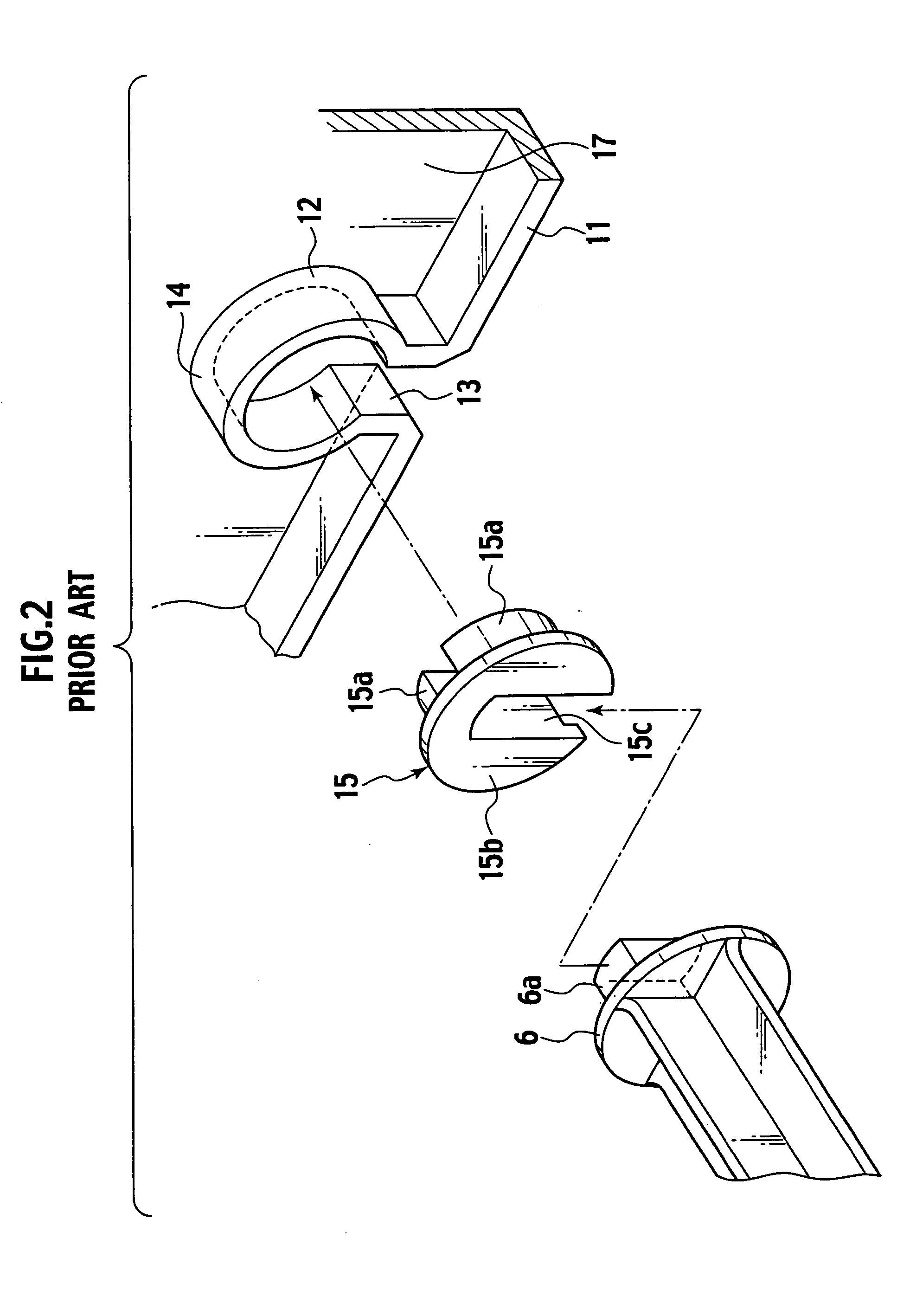
BACKGROUND OF THE INVENTION [0001] 1. Field of the Invention [0002] The present invention relates to a shift lever device installed in a vehicle. [0003] 2. Description of the Related Art [0004] As shown in FIG. 1, this kind of shift lever device for an automatic transmission device includes a resinous base 2 fixed on a vehicle body and a shift lever 1 rotatably supported on the base 2 to allow a range position to be changed with a driver's manipulation. The shift lever 1 includes a rod part 4 rotatably supported on the base 2 and a resinous operating part 5 attached to an upper end of the rod part 4. The rod part 4 is formed with a pivot shaft 6. In assembling, since the pivot shaft 6 is inserted into a recessed groove 13 (see FIG. 2) and supported by the base 2, it becomes possible to construct the whole shift lever 1 being rotatable about the base 2. [0005] In FIG. 1, a not-shown indicator casing is arranged on the top of the base 2, representing respective range positions on a su...

Claims


Application Information

Patent Timeline
Patent Type & Authority Applications(United States)
IPC IPC(8): F16H59/04
CPCF16H59/10F16H2059/026F16H2059/0273Y10T74/2014Y10T74/20085Y10T74/20018Y10T74/2003
Inventor TAKIKAWA, YOSHIHIRO
Owner FUJI KIKO CO LTD
Learn More