Jet flow angle velocity transducer and method for making same

A speed sensor, jet angle technology, applied in the direction of linear/angular velocity measurement, velocity/acceleration/shock measurement, instrument, etc., can solve the problem of large volume, achieve the effect of small volume, compact structure, and avoid wear

Inactive Publication Date: 2005-03-16
PEKING UNIV
View PDF0 Cites 5 Cited by
  • Summary
  • Abstract
  • Description
  • Claims
  • Application Information

AI Technical Summary

Problems solved by technology

The circulating air flow in the jet angular velocity sensor is a gas laminar flow beam excited by a piezoelectric pump, which has a large volume, which limits its application to a large extent
The study of miniaturized jet angular velocity sensor has not been reported yet

Method used


Image

  • Jet flow angle velocity transducer and method for making same
  • Jet flow angle velocity transducer and method for making same
  • Jet flow angle velocity transducer and method for making same

Examples


Embodiment Construction

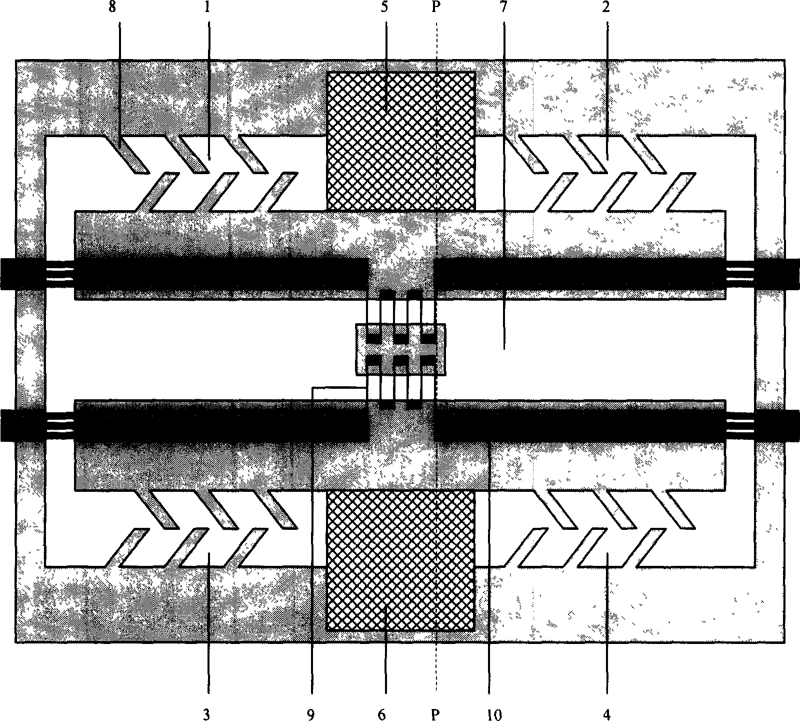
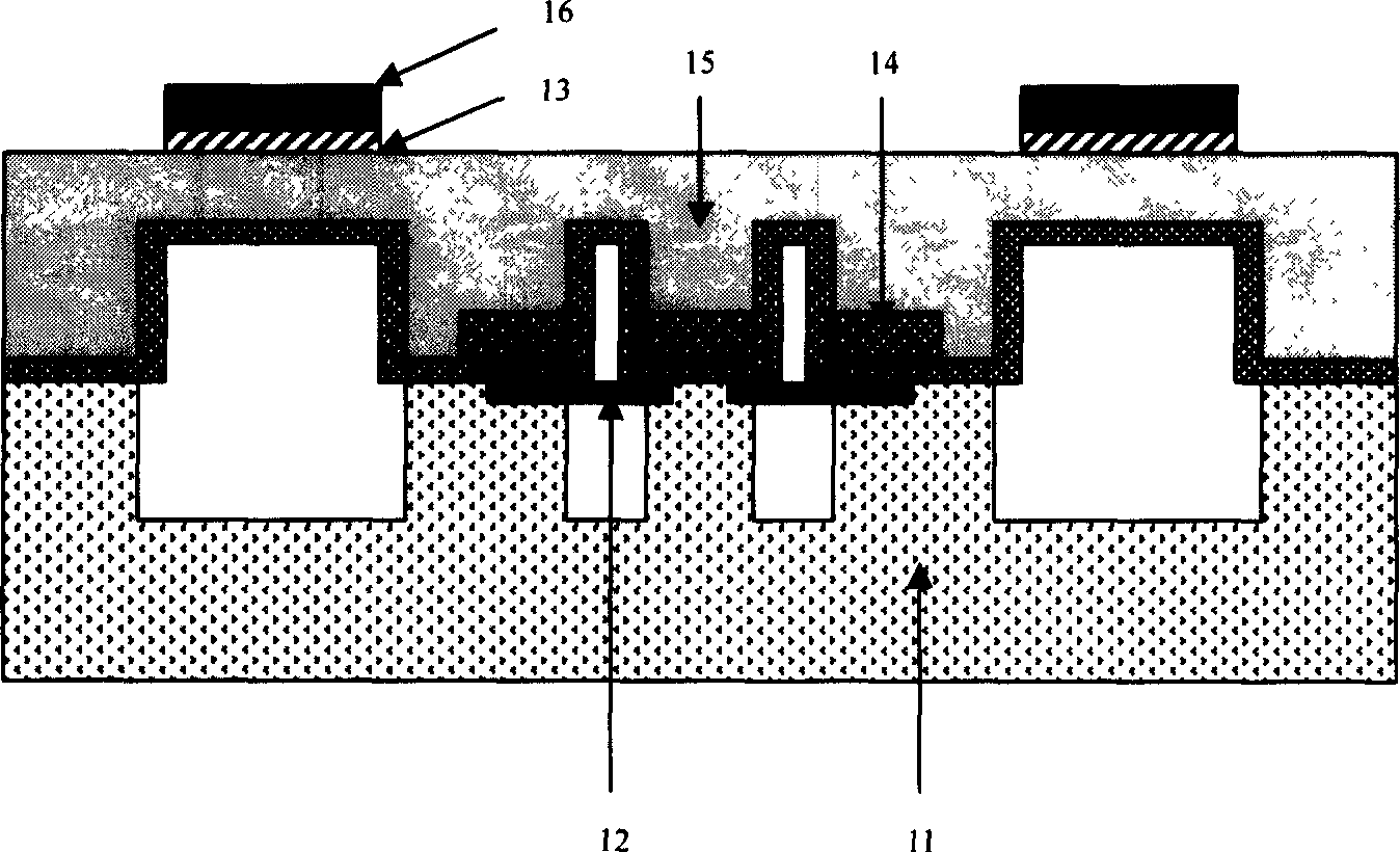
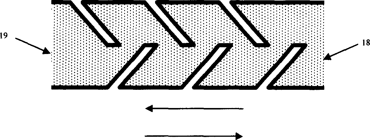
[0032] figure 1 It is a structural schematic diagram of the mace jet angular velocity sensor, figure 2 for figure 1 Cross-sectional view of the P-P plane. It can be seen from the figure that the mace jet angular velocity sensor is composed of four rectifying cavities 1, 2, 3, 4, two vibrating cavities 5, 6, and one detection cavity 7. Two thermistor wires 9 are placed symmetrically in the detection chamber 7 , and the two thermistor wires 9 are connected to a Wheatstone bridge through lead wires 10 . The separation wall below the lead wire 10 not only supports the lead wire, but also isolates the detection chamber 7 from the vibration chambers 5, 6 and the rectification chambers 1, 2, 3, and 4. The four rectification chambers are respectively arranged on both sides of the two vibration chambers, and the detection chamber 7 is located between the two vibrating chambers 5 and 6, each rectifying chamber is a mace fluid diode, and the mace fluid diode is composed of six mace-s...


PUM


Abstract

This invention provides a fluidic angular velocity sensor and its process and belongs to micro electron mechanical system design and its process field. The sensor comprises two vibration chambers; four commute chambers and one detection chamber. The gas in the vibration chamber is driven and recycled and each vibration chamber two sides are located with two commute chambers and the driven gas flows into the detection chamber through the commute chamber and the recycled gas always moves along one direction in the detection chamber. The said detection chamber is symmetrically located with two pieces of heat sensitive resistance wires, which is connected with a Wheatstone bridge. The said commute chamber is needle teeth flow diode, which is composed of several orderly distributed needle teeth block bar.

Description

technical field [0001] The invention belongs to the field of micro-electromechanical system design and processing, and specifically relates to a jet angular velocity sensor and a preparation process thereof. Background technique [0002] The jet angular velocity sensor usually uses the principle of Coriolis force to change the air velocity distribution to detect the angular velocity. Two thermistor wires are symmetrically placed in the detection cavity of the sensor, and the thermistor wires are connected to a Wheatstone bridge. , under the piezoelectric drive or electrostatic drive, the gas inside the chamber can circulate, and the gas in the detection chamber always flows in one direction. When there is no angular velocity input, the gas velocity in the detection chamber exhibits a symmetrical parabolic distribution; when there is angular velocity input, the Coriolis force will cause the gas velocity distribution in the detection chamber to deviate from the parabolic distr...

Claims


Application Information

Patent Timeline
Patent Type & Authority Applications(China)
IPC IPC(8): G01P3/00
Inventor 杨楷周健阎桂珍
Owner PEKING UNIV
Why Eureka
Try Eureka