Three-phase position signal detection method for switched reluctance motor

A switched reluctance motor, signal detection technology, applied in the direction of electronic commutator, etc., can solve the problems of three-phase imbalance, etc., to achieve the effect of correct commutation, good detection accuracy and fast speed

Active Publication Date: 2016-06-01
SOUTHEAST UNIV
View PDF3 Cites 5 Cited by
  • Summary
  • Abstract
  • Description
  • Claims
  • Application Information

AI Technical Summary

Problems solved by technology

This method can avoid the three-phase unbalance caused by the deviation of the position signal in the traditional position detection method, which will cause motor performance problems, and can realize the low error of the position signal detection of the switched reluctance motor, and maintain the balance of the three-phase position signal, so as to realize the correct commutation of the motor, The effect of reliable operation solves the application problem of switched reluctance motor in electric vehicle drive system

Method used


Image

  • Three-phase position signal detection method for switched reluctance motor
  • Three-phase position signal detection method for switched reluctance motor
  • Three-phase position signal detection method for switched reluctance motor

Examples


Embodiment Construction

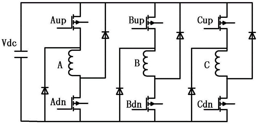
[0028] The specific method and operation process provided by the present invention will be described in detail below in conjunction with the accompanying drawings and examples (taking a three-phase 12 / 8-pole switched reluctance motor as an example).

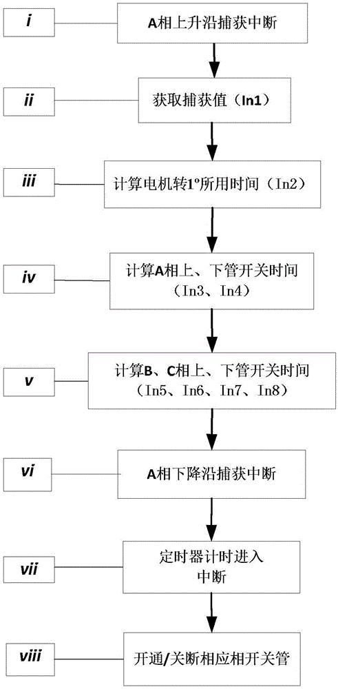
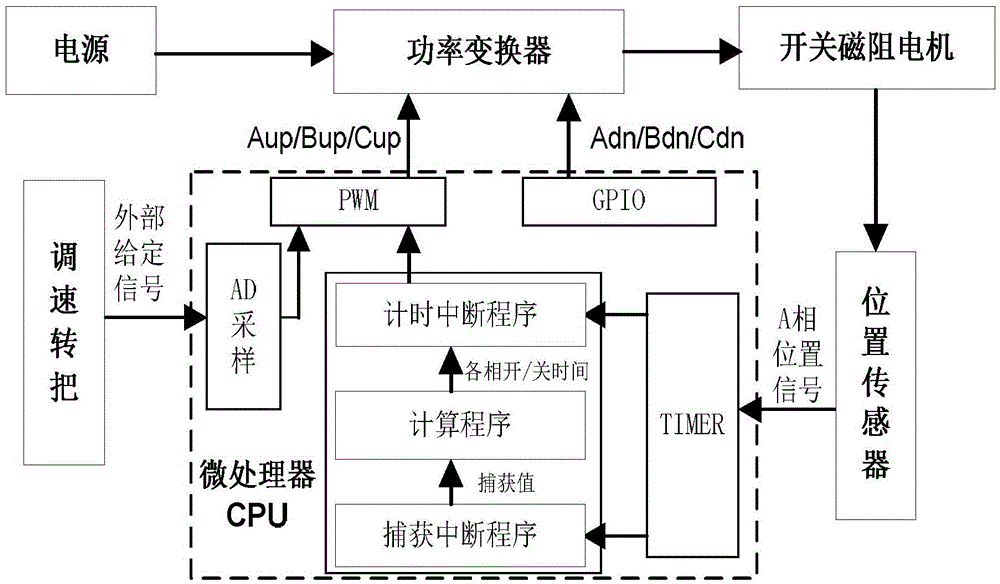
[0029] The structural diagram of the whole switched reluctance motor control system after applying the present invention is as follows figure 2 As shown, it provides power for the entire electric vehicle. Its working principle is that in the high-speed APC mode, the Hall position sensor is used to sample the three-phase position signal of the switched reluctance motor, and the three-phase position signal is sent to the microprocessor CPU, and the general-purpose timer TIM built in the CPU is used to input and capture The channel detects the rising edge of the A-phase Hall position signal, takes the captured value as the reference time, and according to the three-phase switch angle value set in the APC mode, obtains the three-pha...


PUM


Abstract

The invention provides a three-phase position signal detection method for a switched reluctance motor. In a high-speed APC mode, an A phase hall position signal HA is detected by an input capture channel of a universal timer TIM1 to obtain a time interval of a cycle of the position signal; with a capture value as reference time, switching time of three phase switch tubes is calculated according to three-phase switching angle values set in the APC mode; a timer TIM2 starts timing entrance interrupt according to the switching time of each phase; and meanwhile on and off of each phase switch tube of a power converter are controlled and driven by combining a calibration method of capturing a falling edge of the A phase by a timer TIM3, so that operation of the switched reluctance motor is achieved. The method can avoid a hall position signal deviation caused by N, S pole processing errors of other magnet rings, electromagnetic interference and the like, so that the accurate detection result on the three phase hall position signals of the switched reluctance motor is achieved.

Description

technical field [0001] The invention relates to a position signal detection method of a switched reluctance motor, in particular to a three-phase position signal detection method of a switched reluctance motor (SRM), belonging to the technical field of motor control. Background technique [0002] The switched reluctance motor drive system has outstanding features such as simple structure, low cost, flexible control, and good speed regulation performance. It is a new type of speed-adjustable drive system that has developed rapidly with the development of power electronic devices and modern control technology in the past 30 years. . It can maintain high efficiency in a wide range of speed and power, making it play an important role in high-performance applications such as aerospace, electric vehicle drives, household appliances, industry, etc. [0003] In the application of driving systems such as electric vehicles, the driving system controls the running state of the motor a...

Claims


Application Information

Patent Timeline
IPC IPC(8): H02P6/16
CPCH02P6/16
Inventor 钟锐陈青田洪益孙伟锋陆生礼时龙兴
Owner SOUTHEAST UNIV
Why Eureka
Try Eureka