Supercharge Your Innovation With Domain-Expert AI Agents!

FPGA layout method and macro element

A wiring method and layout technology, which is applied in the field of FPGA wiring methods and macro cells, can solve the problems of large memory consumption and increased wiring time, and achieve the effects of reducing wiring time, reducing the number of nodes, and reducing memory consumption

Active Publication Date: 2016-06-01
CAPITAL MICROELECTRONICS
View PDF3 Cites 5 Cited by
  • Summary
  • Abstract
  • Description
  • Claims
  • Application Information

AI Technical Summary

Benefits of technology

This technology allows an ASIC (Application Specific Integrated Circuit) chip designer or programmer to create customized circuits on their own computer without having to manually program them through complex programming languages like C/C++ programs. It also simplifies the routing processes needed when connecting different components together within these circuits. By embedding this circuit design data inside each layer of the device's semiconductor substrate, it becomes easier than ever before to perform detailed simulation analysis due to its unique route from one level to another. Overall, this new technique helps reduce costs associated with laying out integrated circuits while still maintaining high efficiency.

Problems solved by technology

This patented describes how complex electronic devices such as field programmable gate array(FPGAs), have become increasingly important for use across different industries due to their ability to perform various functions quickly and efficiently while being compacted into smaller sizes. However, current methods require manual intervention when create these circuits, leading to increased complexity and cost overruns. Therefore, it becomes crucial to develop efficient techniques by automatically optimizing circuit placement within this type of semiconductor chip called FPGASA.

Method used


Image

  • FPGA layout method and macro element
  • FPGA layout method and macro element
  • FPGA layout method and macro element

Examples


Embodiment Construction

[0022] The technical solutions of the present invention will be described in further detail below with reference to the accompanying drawings and embodiments.

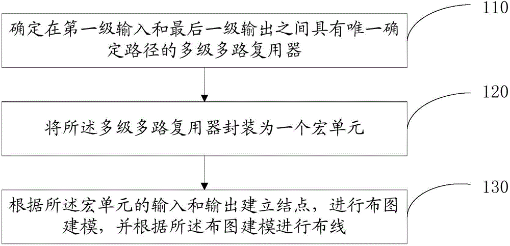
[0023] figure 1 A kind of FPGA wiring method that the embodiment of the present invention provides, described method comprises:

[0024] Step 110, determining a multistage multiplexer with a uniquely determined path (PATH) between the first stage input and the last stage output;

[0025] Wherein, the multi-stage multiplexer includes at least two stages of multiplexers, and each stage of multiplexers includes one or more multiplexers;

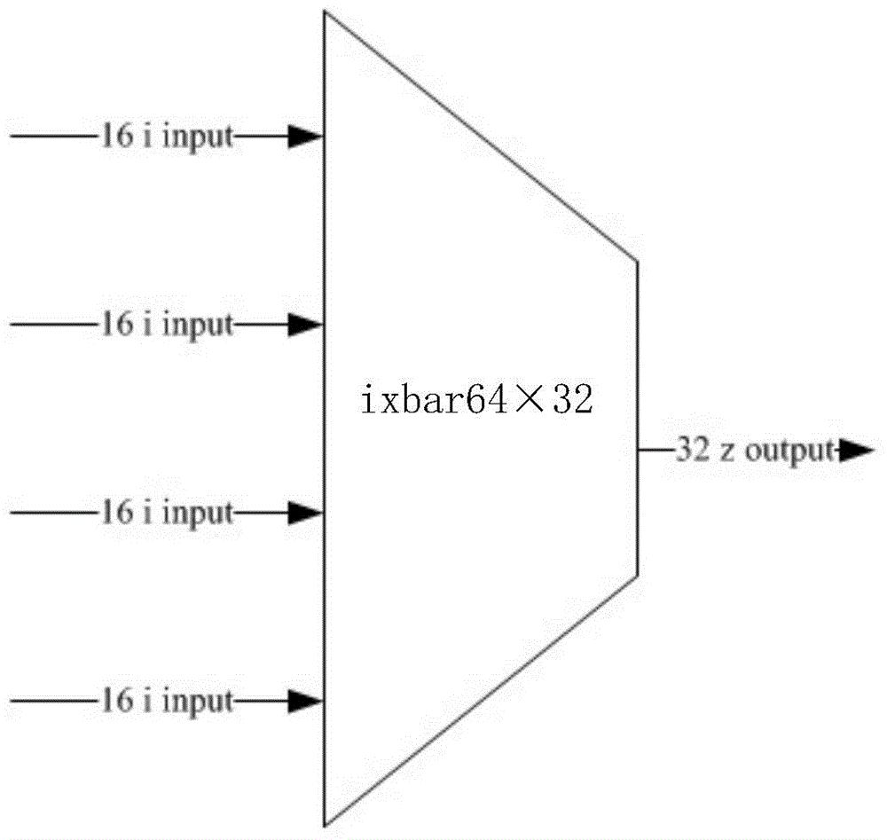
[0026] A case where a multi-stage multiplexer has a uniquely determined path between the input of the first stage and the output of the last stage may be an input crossbar matrix (ixbar) structure composed of multiplexers.

[0027] figure 2 Shown is a specific example of an input crossbar matrix (ixbar) structure with two stages of multiplexers.

[0028] Among them, the first level ...


PUM


Abstract

The invention relates to a FPGA layout method and a macro element. The method comprises steps of: determining multiple stages of multiplexers with a unique determined path and between a first-stage input and a last-stage output, wherein the multistage multiplexer includes at least two stages of multiplexers, each stage of multiplexers includes one or more multiplexers; packaging the multiple stages of multiplexers into a macro element, wherein the input of the macro element is the first-stage input and the output of the macro element is the last-stage output; establishing nodes according to the input and the output of the macro element, setting a layout model, and performing layout according to the layout model.

Description


Claims


Application Information

Patent Timeline
Owner CAPITAL MICROELECTRONICS
Features
  • R&D
  • Intellectual Property
  • Life Sciences
  • Materials
  • Tech Scout
  • Unparalleled Data Quality
  • Higher Quality Content
  • 60% Fewer Hallucinations
Learn More