Thermal insulation switch structure and electric kettle

A technology of switch structure and electric kettle, which is applied to water-boiling utensils, cooking utensils, household utensils, etc., can solve the problems that the structural stability is easily affected by the size of the bottom cover parts, the appearance of industrial design is affected, and the structure of thermal insulation is limited. , to achieve the effect of simple and clear one-key operation, simple structure, and easy failure

Active Publication Date: 2016-06-08
GUANGDONG MIDEA CONSUMER ELECTRICS MFG CO LTD +1
View PDF9 Cites 7 Cited by
  • Summary
  • Abstract
  • Description
  • Claims
  • Application Information

AI Technical Summary

Problems solved by technology

[0002] At present, the switch installation structure of the thermal insulation electric kettle on the market, such as figure 1 and figure 2 As shown, the heat preservation switch 2 is directly installed on the bottom cover, and the structural stability is easily affected by the size of the bottom cover parts; at the same time, the heat preservation indicator light is also arranged on the bottom cover, and is indicated by the light transmission of the heat preservation indicator light cover 1 arranged on the bottom cover; The thermal insulation structure is limited, and the position and size of the switch affect the appearance of the industrial design; in addition, the operation switch and the indicator light are separated, which is not simple and clear enough; especially when it is together with the power indicator light cover 3, it is easier to confuse the indication; it is not convenient for users to use

Method used


Image

  • Thermal insulation switch structure and electric kettle
  • Thermal insulation switch structure and electric kettle
  • Thermal insulation switch structure and electric kettle

Examples


Embodiment Construction

[0049] In order to understand the above-mentioned purpose, features and advantages of the present invention more clearly, the present invention will be further described in detail below in conjunction with the accompanying drawings and specific embodiments. It should be noted that, in the case of no conflict, the embodiments of the present application and the features in the embodiments can be combined with each other.

[0050] In the following description, many specific details are set forth in order to fully understand the present invention. However, the present invention can also be implemented in other ways than described here. Therefore, the protection scope of the present invention is not limited by the specific implementation disclosed below. Example limitations.

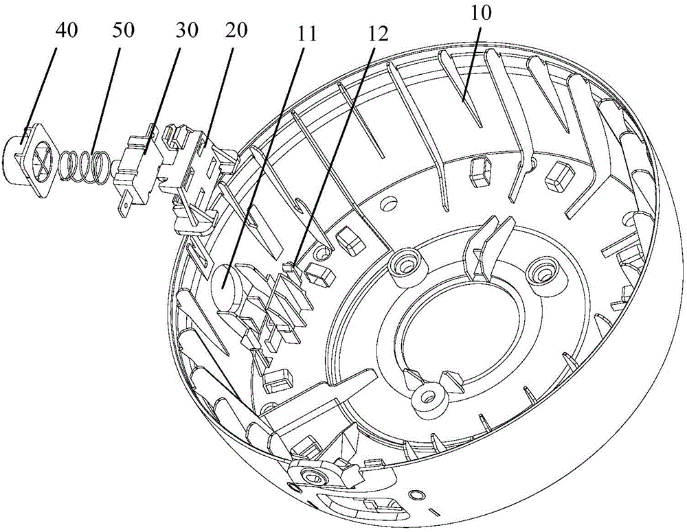
[0051] Such as Figure 3 to Figure 6 As shown, according to the embodiment of the first aspect of the present invention, a heat preservation switch structure is provided for an electric kettle, including: a ...


PUM


Abstract

The invention provides a thermal insulation switch structure and an electric kettle. The thermal insulation switch structure comprises a support assembly and a thermal insulation button. The support assembly is in the bottom cover of the electric kettle. The support assembly comprises a support component and a thermal insulation switch. The thermal insulation switch is assembled on the support component through a button placement structure of the support component. The first end of the thermal insulation button passes through a preset hole of the bottom cover and is in the bottom cover. The first end of the thermal insulation button is provided with an elastic element. The thermal insulation button is connected with the support assembly through the elastic element. Through the technical scheme, the support component and the thermal insulation switch combine to form the support assembly. Compared with the prior art, the position of the support assembly is more flexible, the support assembly is not limited by bottom cover space, and influence of sizes of other components of the bottom cover on the thermal insulation switch is prevented, installation of the thermal insulation switch structure is simplified, so the thermal insulation switch is more stable. A thermal insulation indication lamp cover and the thermal insulation button are combined, and the appearance modeling is simplified, one key operation is simple and clear, and the electric kettle is convenient for a user to use.

Description

technical field [0001] The invention relates to the technical field of household appliances, and more specifically, to a heat preservation switch structure and an electric kettle. Background technique [0002] At present, the switch installation structure of the thermal insulation electric kettle on the market, such as figure 1 and figure 2 As shown, the heat preservation switch 2 is directly installed on the bottom cover, and the structural stability is easily affected by the size of the bottom cover parts; at the same time, the heat preservation indicator light is also arranged on the bottom cover, and is indicated by the light transmission of the heat preservation indicator light cover 1 arranged on the bottom cover; The thermal insulation structure is limited, and the position and size of the switch affect the industrial design appearance; the operation switch is separated from the indicator light, which is not simple enough; especially when it is together with the pow...

Claims


Application Information

Patent Timeline
Patent Type & Authority Applications(China)
IPC IPC(8): A47J36/00A47J27/21
Inventor 陈前
Owner GUANGDONG MIDEA CONSUMER ELECTRICS MFG CO LTD
Why Eureka
Try Eureka