Automatic welding device

A technology for automatic welding and driving motors, which is applied in welding equipment, non-electric welding equipment, metal processing equipment, etc.

Inactive Publication Date: 2016-06-08
SHANGHAI AEROSPACE EQUIP MFG GENERAL FACTORY
View PDF6 Cites 11 Cited by
  • Summary
  • Abstract
  • Description
  • Claims
  • Application Information

AI Technical Summary

Problems solved by technology

[0007] In order to solve the aforementioned problem of friction stir welding of butt ...

Method used


Image

  • Automatic welding device
  • Automatic welding device
  • Automatic welding device

Examples


Embodiment Construction

[0022] The present invention will be further described in detail below in conjunction with the accompanying drawings and embodiments. It should be understood that the following examples are only used to illustrate the present invention but not to limit the scope of the present invention.

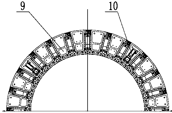
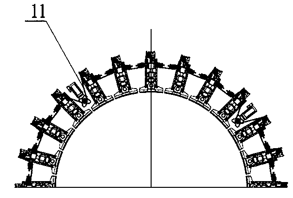
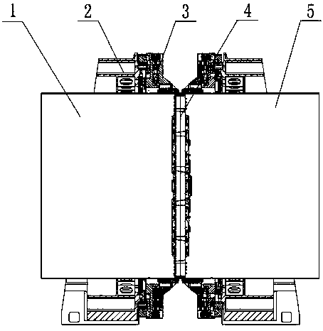
[0023] as attached figure 1 And attached figure 2 As shown, the overall use function of the automatic welding device, such as the left cylinder section 1 of the storage tank and the right cylinder section 5 of the storage tank, are two cylinder sections that need to be butt jointed for circular seam friction stir welding, and the left and right chucks 3 pass through the turntable bearing 6 and The ring guide rail 7 is connected to the rigid support 2, and the pneumatic expansion ring 4 cooperates with the chuck 3 to clamp the left cylinder section 1 of the storage tank and the right cylinder section 5 of the storage tank to form a rigid body, which is driven by the rotary drive mechanism 8...


PUM


Abstract

The invention relates to an automatic welding device. The automatic welding device comprises rigid supporting seats, multi-claw chuck mechanisms, built-in flexible pneumatic piston rings, a rotary table bearing, an annular guide rail and a rotary driving mechanism, wherein the built-in flexible pneumatic piston rings are matched with storage tank drum segments; the multi-claw chuck mechanisms are connected to the rigid supporting seats through the rotary table bearing and the annular guide rail; the flexible pneumatic piston rings and the multi-claw chuck mechanisms are matched with the storage tank drum segments needing butt joint and friction stir welding for circular seams so as to form a rigid body, and the rigid body is driven by the rotary driving mechanism to rotate relative to the rigid supporting seats. According to the automatic welding device disclosed by the invention, the problems that, in the prior art, storage tanks are structural parts with big sizes and thin walls, so that the rigidity of the storage tanks is poor, and the storage tanks are difficult to fix and position are solved, and the automatic welding device has the beneficial effects that the dynamic stability of the welding process of the circular seams is guaranteed, and the welding quality is improved.

Description

technical field [0001] The invention relates to the field of friction stir welding, in particular to an automatic welding device suitable for friction stir welding of tank circular seams. Background technique [0002] Since the invention of friction stir welding, friction stir welding technology has received extensive attention and in-depth research, especially in the field of aerospace applications. Friction stir welding was first used in the welding of the longitudinal seam of the storage tank of the space launch vehicle. At present, the application in this field at home and abroad has achieved complete success. In order to further expand the application of friction stir welding technology and realize the friction stir welding of rocket rockets, foreign countries, such as NASA, Boeing, Japan, etc., have gradually carried out the application of friction stir welding technology on the ring seam of the storage tank. applications are in their infancy. [0003] However, in ...

Claims


Application Information

Patent Timeline
IPC IPC(8): B23K20/12
Inventor 严军富张华德韦叶林永勇郭立杰周法权徐晓霞杨国舜
Owner SHANGHAI AEROSPACE EQUIP MFG GENERAL FACTORY
Why Eureka
Try Eureka