Automatic clamp ring installation mechanism

An automatic installation and snap ring technology, which is applied in metal processing equipment, metal processing, manufacturing tools, etc., can solve the problems of difficulty in ensuring the position accuracy of snap rings, low installation efficiency, and high difficulty in fixture design

Active Publication Date: 2016-06-08
YUANTAI AUTOMATION TECH SUZHOU
View PDF9 Cites 4 Cited by
  • Summary
  • Abstract
  • Description
  • Claims
  • Application Information

AI Technical Summary

Problems solved by technology

For the smaller snap ring, due to the narrow space for snapping into the product, it is difficult to install manually, and the design of the jig to open the snap ring is difficult. In the prior

Method used


Image

  • Automatic clamp ring installation mechanism
  • Automatic clamp ring installation mechanism
  • Automatic clamp ring installation mechanism

Examples


Example Embodiment

[0023] Examples:

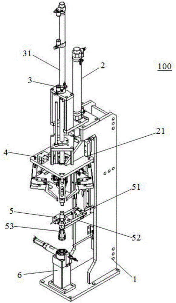
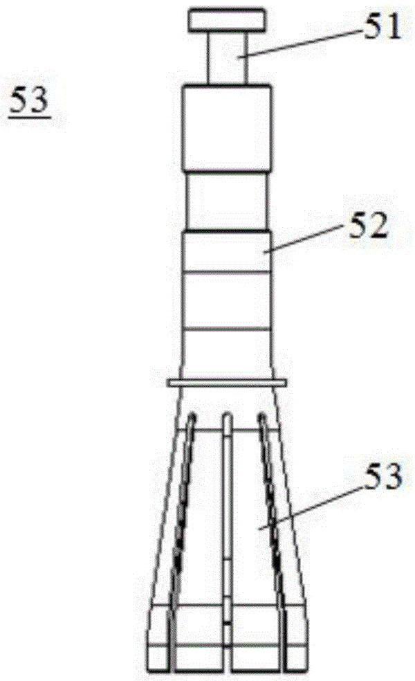
[0024] Please refer to Figure 1-Figure 3 In this embodiment, an automatic snap ring installation mechanism 100 includes a bracket 1, a first air cylinder 2 fixed on the bracket 1, a grasping device 3, a pushing device 4 that is driven by the first air cylinder 2 to move up and down, and a fixed On the support 1 and under the grasping device 3, a guide bearing device 5 for inductive positioning of the snap ring, and a positioning table 6 under the guide bearing device 5 for fixing the product to be installed.

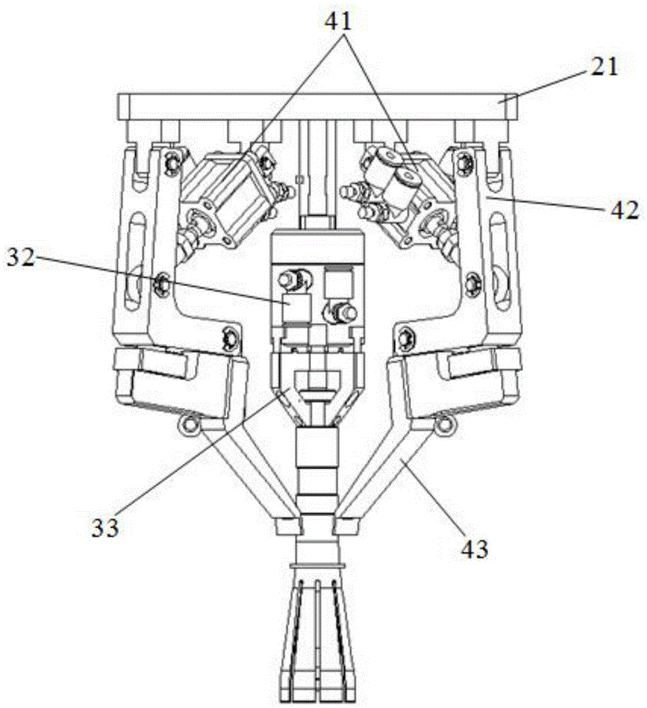
[0025] The movable end of the first cylinder 2 is provided with a connecting plate 21 that moves up and down on the support 1. The grasping device 3 includes a second cylinder 31 fixed on the support 1 and a third cylinder 32 that is driven by the second cylinder 31 to move up and down. , The first jaw 33 driven by the third cylinder 32 to open or close.

[0026] The pushing device 4 includes four fourth cylinders 41 fixed on the lower surface of the conne...


PUM


Abstract

The invention discloses an automatic clamp ring installation mechanism which comprises a bracket, a first cylinder, a gripping device, a guide bearing device, and a pushing-in device, wherein the first cylinder, the gripping device and the guide bearing device are fixedly on the bracket; the pushing-in device is driven by the first cylinder to move up and down; the guide bearing device comprises a fifth cylinder, a third clamping jaw driven by the fifth cylinder to take opening and closing actions, and a guide jig clamped by the third clamping jaw; and from top to bottom, the guide jig comprises a clamping part, a guide part and a hollow cone part with a plurality of gaps formed in the surface. According to the automatic clamp ring installation mechanism disclosed by the invention, the cone part with the gaps in the surface is arranged in the guide jig, and thus, on one hand, by utilizing the characteristic that the diameter of the cone part is gradually increased from top to bottom, a clamp ring can be supported and prevented from falling off so as to achieve bearing on the clamp ring; and on the other hand, by utilizing the condition that the cone part can shrink inwards, the cone part is matched with a second clamping jaw to push the clamp ring sleeving the cone part into a product to be installed, so that the defects of difficulty in gripping due to a small size of the clamp ring and difficulty in installation due to a narrow and small installation space are overcome.

Description

【Technical field】 [0001] The invention belongs to the technical field of snap ring assembly, in particular to a snap ring automatic installation mechanism. 【Background technique】 [0002] The clasp is the main retainer of the removable denture restoration. It is directly clamped on the main abutment teeth and is made of metal to play the role of retention, stability and support. For the smaller snap ring, due to the narrow space for snapping into the product, it is difficult to install manually, and the design of the jig to open the snap ring is difficult. In the prior art, the installation of the snap ring has always been manual installation, and the installation efficiency Low, and the positional accuracy of snap ring installation is difficult to guarantee. [0003] Therefore, it is necessary to provide a new snap ring automatic installation mechanism to solve the above problems. 【Content of invention】 [0004] The main purpose of the present invention is to provide an...

Claims


Application Information

Patent Timeline
IPC IPC(8): B23P19/027
CPCB23P19/027
Inventor 贺竞人王连义刘名孙靖
Owner YUANTAI AUTOMATION TECH SUZHOU
Why Eureka
Try Eureka