
Acetabulum parastyle and posterior column united steel plate

A technology of anterior and posterior columns and steel plates, applied in the direction of outer plates, internal bone synthesis, fixers, etc., can solve problems such as increased infection rates, excessive bleeding, and redisplacement of fracture fragments

Inactive Publication Date: 2014-12-10
王钢
View PDF11 Cites 22 Cited by
  • Summary
  • Abstract
  • Description
  • Claims
  • Application Information

AI Technical Summary

Problems solved by technology

However, there is the first technical problem as follows: due to the deep anatomical position of the acetabulum and the complex adjoining anatomical relationship, the traditional surgery and internal fixation methods are too focused on the reduction of the fracture and the stability of the fixation, and then ignore the long incision and extensive exposure. , a lot of bleeding, and many postoperative complications, such as iatrogenic sciatic nerve injury, heterotopic ossification, femoral head necrosis, etc.
[0004] For acetabular fractures that involve both the anterior and posterior columns, the past treatment can be through a single posterior K-L approach with double plate fixation of the posterior column, but there is a second technical problem as follows: this often results in loss of postoperative reduction, resulting in fractures The redisplacement of the block, and finally the internal fixation failure
[0005] There is also an anterior-posterior joint approach, where the anterior and posterior columns are respectively fixed with reconstruction plates. After this method is fixed, there is a third technical problem as follows: the anterior and posterior columns are only fixed separately, and there is still a gap between the anterior and posterior columns. Lack of connection, and because of the large surgical trauma, it is easy to cause more bleeding during the operation, increase the chance of infection, and the incidence of complications such as postoperative heterotopic ossification, and ultimately still cause a great adverse effect on the joint function of the patient
[0006] The applicant's previous application, a navigation template for implanting acetabular posterior column screws (publication number CN102657553A), But there are several technical problems as follows: In clinical practice, acetabular fractures often involve the anterior column and the posterior column at the same time, and the navigation template for implanting the posterior acetabular column screw is only used for safe and accurate implantation of the posterior acetabular column screw. It needs to be taken out of the body, and it cannot solve the fixation of the anterior column at the same time. The pure posterior column lag screw fixation does not have the blocking function of the square area, let alone the combined fixation of the anterior and posterior columns of the acetabulum.
[0007] To sum up, there is currently no implantable internal fixation device that can accurately and safely fix the anterior and posterior columns of the acetabulum simultaneously through a single surgical approach, and maintain the relationship between the anterior and posterior columns. The connection between the front column and the back column is fixed as a whole, and at the same time, it has the function of blocking the square area and preventing the fracture block from shifting into the pelvic cavity again

Method used


Image

  • Acetabulum parastyle and posterior column united steel plate
  • Acetabulum parastyle and posterior column united steel plate
  • Acetabulum parastyle and posterior column united steel plate

Examples


Embodiment Construction

[0025] The present invention will be further described below in conjunction with drawings and embodiments.

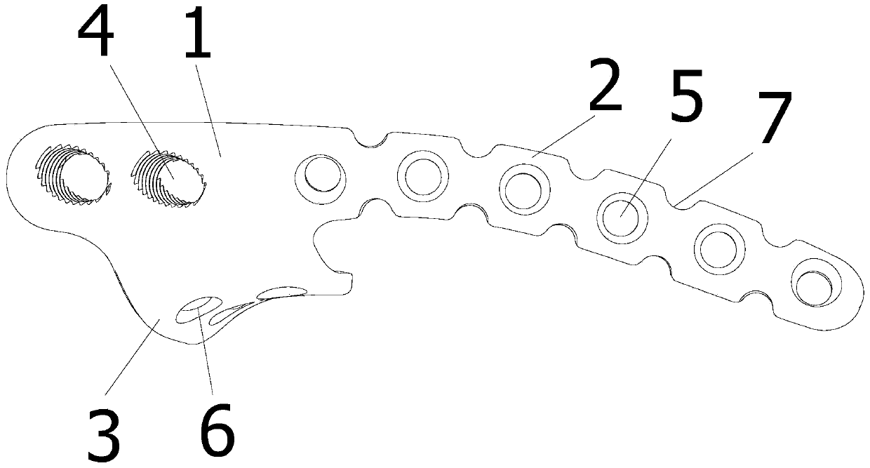
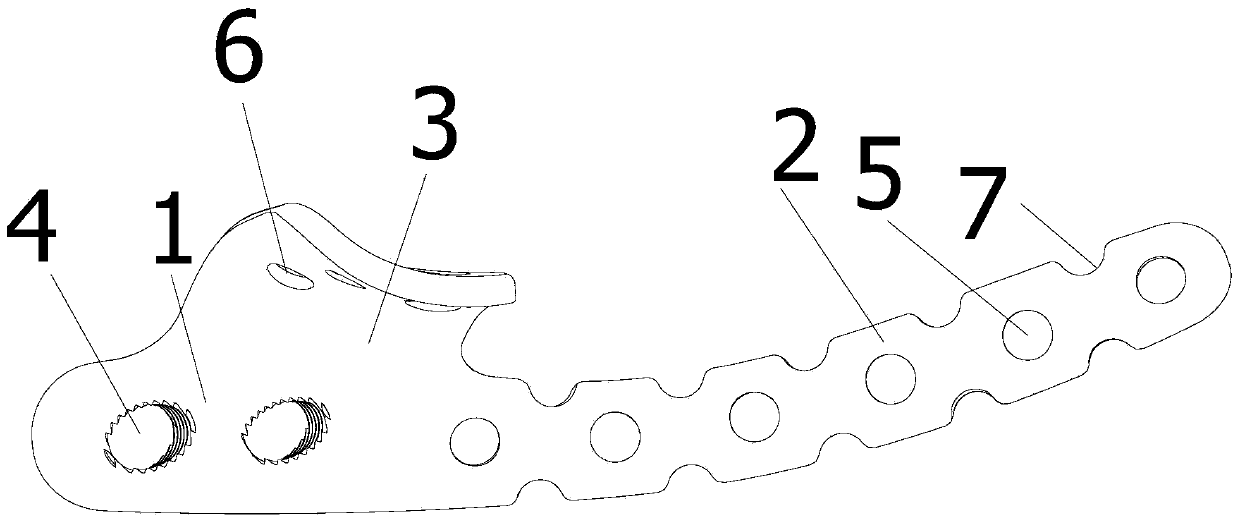
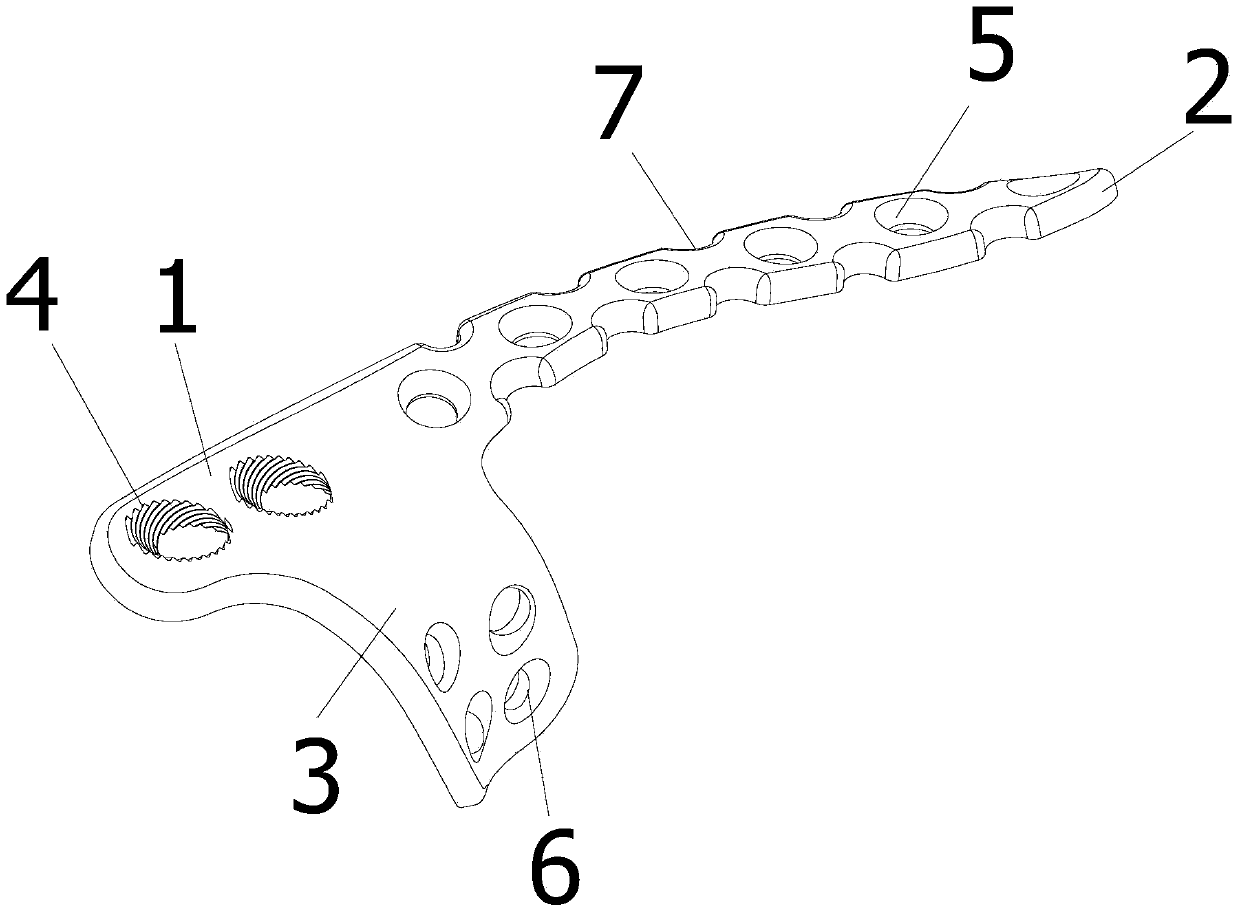
[0026] Such as Figure 1 to Figure 4 The combined plate of the anterior and posterior columns of the acetabulum shown is composed of the main plate 1, the anterior column plate 2 and the baffle plate 3, wherein,

[0027] The main board 1 is provided with two threaded holes 4 connected to the rear column locking screw sleeve 14, the threaded holes 4 are arranged along the arcuate edge 12 from the proximal arcuate edge surface 9 of the iliac fossa, and each threaded hole 4 the axis is vertical;

[0028] The baffle plate 3 is formed by one side of the main board 1 bending downwards and extending to the square area 11 above the ischial spine 15, and the curved surface formed by the lower surfaces of the two is compatible with the corresponding arcuate edge surface 9 of the iliac fossa. The surface of a segment of the arcuate edge 12 from the front edge of the sacroiliac j...


PUM

PropertyMeasurementUnit
Diameteraaaaaaaaaa
Diameteraaaaaaaaaa
Thicknessaaaaaaaaaa

Abstract

The invention discloses an acetabulum parastyle and posterior column united steel plate. The united steel plate is composed of a main plate, a parastyle steel plate and a baffle which are connected into a whole. At least two threaded holes are formed in the main plate and are arranged along the bow-shaped edge from the proximately-bow-shaped edge face of the fossa iliaca. The axis of each threaded hole is vertical. One side of the main plate is bent downwards and extends to the square area above the ischial spine to form the baffle. The curved surface formed by the lower surface of the baffle and the lower surface of the main plate is matched with the curved surface formed by the corresponding proximately-bow-shaped edge face of the fossa iliaca, the surface of a bow-shaped edge from the front edge of the sacroiliac joint and the surface of the square area above the ischial spine of the acetabulum bone. A plurality of fixed screw holes are formed in the baffle. The parastyle steel plate extends to the ramus superior ossis pubis from one end of the main plate along the surface of the proximately-bow-shaped edge face of the fossa iliaca. A parastyle fixing screw hole is formed in the parastyle steel plate. The bone fracture plate is easy and convenient to operate, high in safety, small in operation wound, and capable of being used for simultaneously drawing in fractured acetabulums of the parastyle and the posterior column.

Description

technical field [0001] The invention relates to a surgical instrument, in particular to a fixed steel plate for the acetabular and surrounding structures, and the combined steel plate is suitable for fracture repair of the anterior column and the posterior column of the acetabulum. Background technique [0002] The acetabular and surrounding structures can be divided into an anterior column and a posterior column. The anterior column is obliquely forward and downward from the upper part of the iliac crest, and ends at the pubic symphysis through the pubic ramus, and is composed of part of the ilium and pubic bone; the posterior column is formed by the greater notch of the sciatic bone through the acetabulum From the center to the ischial tuberosity, including the vertical portion of the ischium and part of the ilium connected to the ischium; the anterior and posterior columns are in an inverted “Y” shape, cradle-like to hold the acetabulum, and meet on the medial side in the ...

Claims


Application Information

Patent Timeline
IPC IPC(8): A61B17/80
CPCA61B17/8038A61B17/8061A61B17/808
Inventor 王钢洪顾麒高波华
Owner 王钢
Learn More