Self-adjusting anti-deflection hammer

A hammer and anti-bias technology, applied in hand hammers, manufacturing tools, striking tools, etc., can solve the problems of accidentally injuring the fingers of the surrounding people and users, not being on the axis of the nail, and the hammer hitting the fingers, etc. The probability of injuring fingers, preventing deflection, and the effect of preventing deflection of the hammer head

Active Publication Date: 2016-06-08
南通旭辉模具有限公司
View PDF5 Cites 4 Cited by
  • Summary
  • Abstract
  • Description
  • Claims
  • Application Information

AI Technical Summary

Problems solved by technology

[0002] Hammer is one of the commonly used tools in daily life; it is widely used in decoration, processing, maintenance and other fields; when using a hammer to ram a nail, it is often necessary to hold the nail with one hand and raise the hammer with the other hand to hit it. In the process of tamping, the hammer is often deflected and the finger is injured; sometimes it is because the hammer's landing point is not correct, the center of gravity of the hammer head is not on the axis of the nail, and the hammer head deflects under the action of inertial force after touching the nail. Cause the nails to fly, accidentally injuring the surrounding crowd and the user's fingers; therefore, the current common hammer has a greater safety hazard during use

Method used


Image

  • Self-adjusting anti-deflection hammer
  • Self-adjusting anti-deflection hammer

Examples


Embodiment

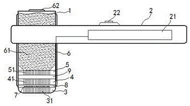
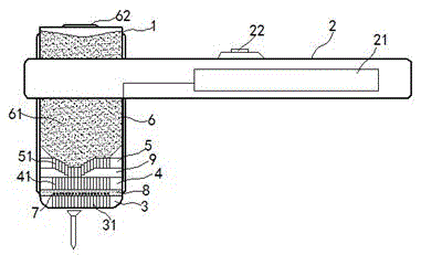
[0019] exist figure 1 , figure 2 In the shown embodiment, the self-adjusting anti-deflection hammer includes two parts: a hammer head 1 and a hammer handle 2; the hammer handle 2 is fixedly installed on the hammer head 1; 21, a control switch 22 is also installed on the hammer handle 2;

[0020] The lower part of the hammerhead 1 includes a hammering plate 3, on which hammering columns 31 are arranged in an equidistant array, each of the hammering columns 31 is parallel to each other, and each hammering column 31 Perpendicular to the plate surface of the hammering plate 3; an electromagnetic plate 4 is installed above the hammering plate 3, and electromagnetic columns 41 are arranged in an equidistant array on the electromagnetic plate 4; Permanent magnet plate 5, permanent magnet columns 51 are arranged in an equidistant array on the permanent magnet plate 5, and the magnetic pole direction of each described electromagnetic column 41 is consistent and can translate up and ...


PUM


Abstract

The invention relates to a self-adjusting anti-deflection hammer. The self-adjusting anti-deflection hammer comprises a hammer head and a hammer handle; the lower portion of the hammer head is provided with a hammering plate, and hammering columns are distributed on the hammering plate; an electromagnetic plate is installed over the hammering plate, and a permanent magnetic plate is installed over the electromagnetic plate; electromagnetic columns are distributed on the electromagnetic plate, permanent magnetic columns are distributed on the permanent magnetic plate, the magnetic pole directions of all the electromagnetic columns are consistent, and the electromagnetic columns can horizontally move up and down along the axes of the electromagnetic columns; a counterweight cavity is formed over the permanent magnetic plate; a pressure-sensitive plate is laid between the hammering plate and the electromagnetic plate, pressure-sensitive sheets are distributed on the pressure-sensitive plate at equal distance in an array mode, and the pressure-sensitive sheets are correspondingly matched with the hammering columns and the electromagnetic columns one to one; the pressure-sensitive sheets and the electromagnetic columns are paired one to one and electrically connected. The hammer is exquisite in structure and novel in principle, hammer head deflection is effectively prevented, and the ramming efficiency and the using safety are greatly improved.

Description

technical field [0001] The invention relates to a hardware product, especially a hammer. Background technique [0002] Hammer is one of the commonly used tools in daily life; it is widely used in decoration, processing, maintenance and other fields; when using a hammer to ram a nail, it is often necessary to hold the nail with one hand and raise the hammer with the other hand to hit it. During the tamping process, the hammer often deflects and hurts the fingers; sometimes it is because the drop point of the hammer is not correct, the center of gravity of the hammer head is not on the axis of the nail, and the hammer head deflects under the action of inertial force after touching the nail. Cause the nails to fly, and accidentally injure the surrounding crowd and the user's fingers; therefore, there is a relatively large safety hazard in the use of the current common hammer. Contents of the invention [0003] In view of the above problems, the present invention provides...

Claims


Application Information

Patent Timeline
Patent Type & Authority Applications(China)
IPC IPC(8): B25D1/02B25D1/00
CPCB25D1/00B25D1/02
Inventor 仲杏英
Owner 南通旭辉模具有限公司
Why Eureka
Try Eureka