Supercharge Your Innovation With Domain-Expert AI Agents!

Optical ranging system and method

An optical ranging and ranging method technology, applied in the field of ranging systems, can solve the problems of insufficient exposure, inability to calculate the distance of a long-distance object to be measured, and reduced calculation accuracy of the optical ranging system.

Active Publication Date: 2018-02-09
PIXART IMAGING INC
View PDF6 Cites 0 Cited by
  • Summary
  • Abstract
  • Description
  • Claims
  • Application Information

AI Technical Summary

Problems solved by technology

[0003] However, when there are multiple UUTs with different distances in the space at the same time, the near-distance UUTs may have over exposure, while the far-distance UUTs may have underexposure. ), the calculation accuracy of the optical ranging system may be reduced
In particular, when the exposure of the distant object under test is insufficient, there will be a problem that the object distance of the distant object cannot be calculated

Method used


Image

  • Optical ranging system and method
  • Optical ranging system and method
  • Optical ranging system and method

Examples


Embodiment Construction

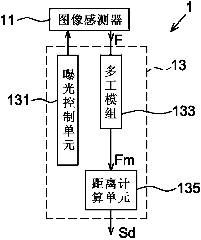
[0038] Please refer to figure 1 As shown, it is a schematic block diagram of an optical ranging system according to an embodiment of the present invention. The optical ranging system 1 includes an image sensor 11 and a processing unit 13 . The image sensor 11 is preferably an active image sensor, such as a complementary metal-oxide-semiconductor (CMOS) image sensor, which can change the exposure time when acquiring the image F or use multiple The exposure time respectively acquires different image areas of the image F (examples will be described in detail later).

[0039] The processing unit 13 can be, for example, a digital signal processor (DSP), a single chip (MCU), a central processing unit (CPU), etc., for receiving the image F output by the image sensor 11 for post-processing, And control the image acquisition of the image sensor 11 . In one embodiment, the processing unit 13 may include an exposure control unit 131 , a multiplexing module 133 and a distance calculati...


PUM


Abstract

An optical ranging system includes an image sensor and a processing unit. The processing unit generates an image to be calculated according to at least one image acquired by the image sensor; wherein different image regions of the image to be calculated correspond to different exposure times, so as to increase the accuracy of distance calculation.

Description

technical field [0001] The present invention relates to a ranging system, and more particularly, to an optical ranging system and method using a multiplex exposure mechanism. Background technique [0002] Optical ranging systems use triangulation to calculate distances to objects. For example, an optical rangefinder system may include a light source and a camera. The light source projects light toward the object to be tested, and the camera receives the reflected light from the object to be tested to form an image frame. When the spatial relationship between the light source and the camera is known, the distance of the object to be measured can be calculated according to triangulation according to the image position of the object in the image frame. [0003] However, when there are multiple objects to be tested at different distances in the space at the same time, the objects to be tested at close distances may be over exposed, and the objects to be tested at long distance...

Claims


Application Information

Patent Timeline
Patent Type & Authority Patents(China)
IPC IPC(8): G01C3/00
Inventor 王国振
Owner PIXART IMAGING INC
Features
  • R&D
  • Intellectual Property
  • Life Sciences
  • Materials
  • Tech Scout
  • Unparalleled Data Quality
  • Higher Quality Content
  • 60% Fewer Hallucinations
Learn More