
Explosion speed test system and method for explosives

A technology of explosion velocity and test system, which is applied in the direction of using a device that measures the time required to move a certain distance, can solve the problems of inconvenience in carrying, cumbersome operation, limited number of test probes used at one time, etc. Effect

Active Publication Date: 2018-11-06
ANHUI UNIV OF SCI & TECH
View PDF9 Cites 0 Cited by
  • Summary
  • Abstract
  • Description
  • Claims
  • Application Information

AI Technical Summary

Problems solved by technology

However, the time measuring instrument method needs to connect a lot of cables to the explosives to transmit electrical signals. If they cannot be connected incorrectly, the test data will not be obtained. According to the difference of the time measuring instrument wiring board, the number of probes used for one test is very limited.
In addition, a time measuring instrument is needed during the test, and the whole set of device is cumbersome to operate and inconvenient to carry

Method used


Image

  • Explosion speed test system and method for explosives
  • Explosion speed test system and method for explosives

Examples


Embodiment 1

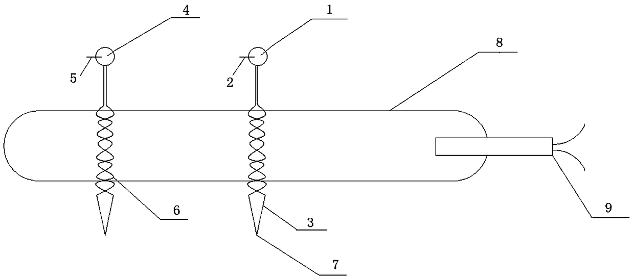
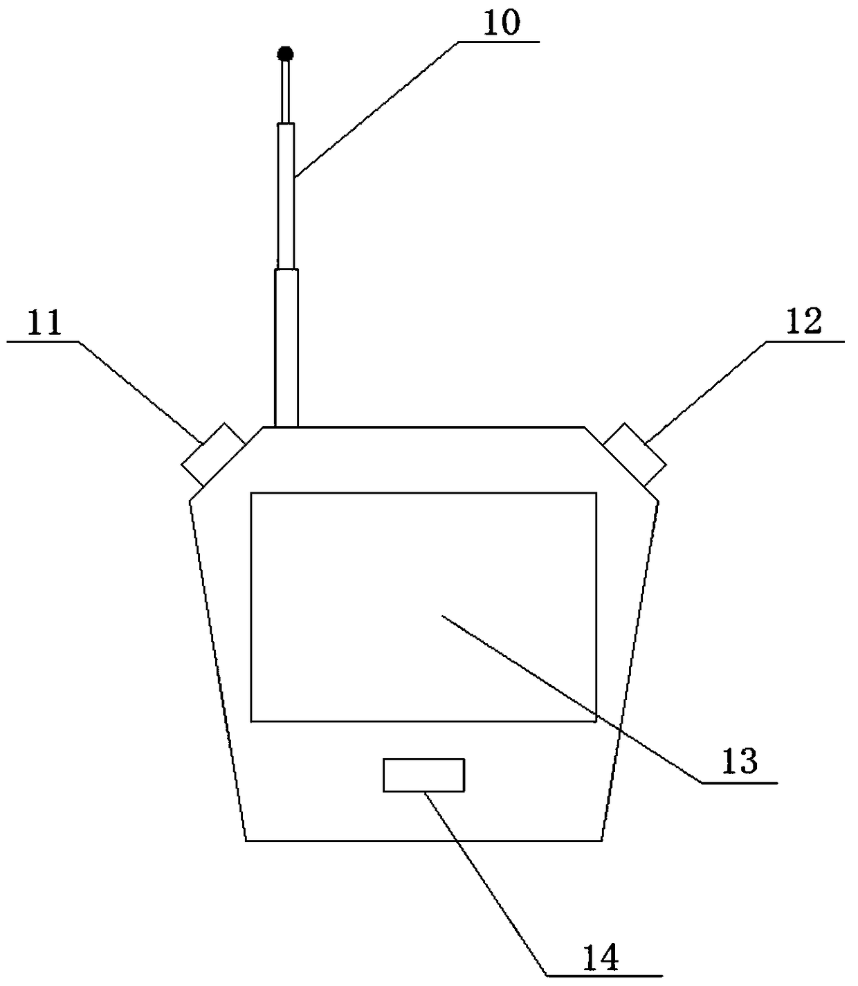
[0034] like figure 1 and figure 2 Shown, the explosive detonation speed testing system of the present invention comprises electromagnetic wave signal receiving device, and two electromagnetic wave signal generating devices (the first electromagnetic wave signal generating device 1 and the second electromagnetic wave signal generating device 4) that communicate with it are provided at intervals; The first electromagnetic wave signal generating device 1 is an example. The first electromagnetic wave signal generating device 1 forms a loop through a section of first enameled wire 3 intertwined with each other. The first electromagnetic wave signal generating device 1 is internally provided with a first power supply. The first power supply and the first enameled wire 3 is provided with a layer of first film 2 for isolating the two. The end of the first enameled wire 3 away from the first electromagnetic wave signal generating device 1 is pointed, and the pointed end 7 passes thro...

Embodiment 2

[0043] An explosive detonation velocity testing system is provided with multiple (more than two) electromagnetic wave signal generating devices and corresponding enameled wires, etc., and the rest are the same as in Embodiment 1.

[0044] The method for testing the detonation velocity of explosives corresponding to this system, the basic steps are the same as embodiment 1, the difference is:

[0045] In step (2), a plurality of electromagnetic wave signal generating devices and corresponding enameled wires are arranged in turn, and the distance between each adjacent two enameled wires is recorded, and then in step (4), it is recorded in turn that the electromagnetic wave signal receiving device receives a plurality of enameled wires. The time of the electromagnetic wave signal, and finally calculate the explosive detonation velocity v' between any adjacent enameled wires according to the formula: v'=D' / (T N+1 -T N ), where N is an integer greater than or equal to 1, T N+1 -T...


PUM


Abstract

The invention discloses an explosive explosion speed test system and a method thereof. A system structure is simple, measurement is accurate, making is convenient, cost is low and carrying is easy. The explosive explosion speed test system comprises an electromagnetic wave signal receiving apparatus and an electromagnetic wave signal generating device which is communicated with the electromagnetic wave signal receiving apparatus and is arranged with the electromagnetic wave signal receiving apparatus in at least two intervals mode. The electromagnetic wave signal generating device forms a loop via a segment of mutually-twined enameled wire. A power supply is arranged in the electromagnetic wave signal generating device. A layer of film used for isolating the power supply and the enameled wire is arranged between the power supply and the enameled wire.

Description

technical field [0001] The invention relates to an explosive detonation velocity test system, in particular to an explosive detonation velocity test system and method. Background technique [0002] The detonation velocity is the propagation speed of the detonation wave in the explosive. Among the parameters calculated by detonation waves, detonation velocity is the only parameter that can be accurately measured by a relatively simple method. Experimental research on the relationship between detonation velocity, detonation conditions and charge properties can provide important basis for research on detonation mechanism, detonation product state equation and explosive product quality. [0003] In the prior art, the most commonly used ones are the chronograph method, the detonating cord method, the continuous oscillometric method, and the embedded pressure probe method. In the detonation velocity determination standard of explosives, it is stipulated that the timing instrumen...

Claims


Application Information

Patent Timeline
Patent Type & Authority Patents(China)
IPC IPC(8): G01P3/66
CPCG01P3/66
Inventor 杨欢高圣涛钱海
Owner ANHUI UNIV OF SCI & TECH
Learn More