
Cable placement frame

A technology for placing racks and cables, which is applied in the direction of pipe supports, electrical components, pipes/pipe joints/fittings, etc., which can solve the problems of large space occupation, unfavorable laying, easy to scatter cables, etc., and achieve simple structure, beautiful appearance and space saving Effect

Inactive Publication Date: 2016-06-08
王帅
View PDF0 Cites 2 Cited by
  • Summary
  • Abstract
  • Description
  • Claims
  • Application Information

AI Technical Summary

Problems solved by technology

[0002] In the construction of electric power engineering, it is usually necessary to lay large-diameter cables in a small space, but if the distance between the cables is too close, it will affect the heat dissipation of the cables, which will easily lead to the aging of the cables, while if the distance between the cables is too sparse, it will take up a lot of space, making the cables easy to scatter. At the same time, the removal of waste cables is also a problem that plagues the construction
[0003] At present, in the laying of the cables in the cable rack, all the cables are arranged on the same surface, so when there are a large number of cables, a large amount of space is often required to lay the cables, and the area and volume passing through the cable rack are also large, which is not conducive to laying. When the space allowed for laying is small, this flat laying method cannot satisfy the laying of all cables

Method used


Image

  • Cable placement frame

Examples


Embodiment 1

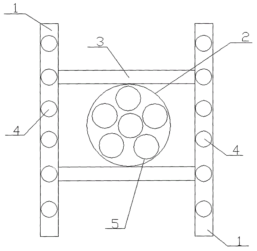
[0017] A cable placement frame provided in this embodiment has a structure such as figure 1 As shown, including the placement frame body 1 and the placement frame arranged on the placement frame body 1, the placement frame body 1 is two wooden poles arranged in parallel, six first threaded holes 4 are provided on the wooden pole, and the first screw thread The holes 4 are evenly distributed on the wooden pole, and there are also square through holes on the inner side of the wooden pole. The placement frame is composed of a fixed sleeve 2 and a fixed bracket 3 fixedly connected to the upper and lower ends of the fixed sleeve 2. The two ends of the fixed bracket 3 extend There are fixed projections, and the placement frame is inserted on the placement frame body 1 through the fixed projections at both ends of the fixed bracket 3. The fixed projections are provided with a second threaded hole that matches the first threaded hole 4 on the wooden pole. The sleeve 2 has a circular s...


PUM


Abstract

The invention relates to a cable placement frame comprising a placement frame body and a placement box arranged on the placement frame body. The placement frame body is composed of two wooden bars arranged in parallel. The wooden bars are each provided with at least four first threaded holes, and the inner sides of the wooden bars are provided with square through holes. The placement box is composed of a fixed sleeve and fixed brackets which are fixedly connected to the upper and lower ends of the fixed sleeve. Fixed bumps extend from the two ends of each fixed bracket respectively, and each fixed bump is provided with a second threaded hole. The fixed sleeve is internally provided with at least six cable holes which are circular, wherein the centers of five cable holes are on the same circumference, and the other cable hole is arranged in the middle of the five cable holes. The cable placement frame has a simple structure and a beautiful shape. With the cable placement frame, cables can be placed properly and gathered together to save space. Moreover, the cable placement frame is of lower friction, and has a longer service life.

Description

technical field [0001] The invention relates to the field of cable placement equipment, in particular to a cable placement frame. Background technique [0002] In the construction of electric power engineering, it is usually necessary to lay large-diameter cables in a small space, but if the distance between the cables is too close, it will affect the heat dissipation of the cables, which will easily lead to the aging of the cables, while if the distance between the cables is too sparse, it will take up a lot of space, making the cables easy to scatter. At the same time, the removal of waste and old cables is also a problem that plagues the construction. [0003] At present, in the laying of the cables in the cable rack, all the cables are arranged on the same surface, so when there are a large number of cables, a large amount of space is often required to lay the cables, and the area and volume passing through the cable rack are also large, which is not conducive to laying....

Claims


Application Information

Patent Timeline
Patent Type & Authority Applications(China)
IPC IPC(8): H02G3/02F16L3/00
Inventor 王帅
Owner 王帅
Learn More