Check patentability & draft patents in minutes with Patsnap Eureka AI!

Input signal intensity display circuit for avalanche photodiode (APD) in light receive module

An optical receiving module and a technology for inputting signals, applied in the field of optical communication, can solve the problems of complex application of peripheral systems and inability to display the intensity of input signals of avalanche photodiodes, and achieve the effect of simple requirements and simple applications

Active Publication Date: 2016-06-08
FENGHUO COMM SCI & TECH CO LTD
View PDF6 Cites 1 Cited by
  • Summary
  • Abstract
  • Description
  • Claims
  • Application Information

AI Technical Summary

Problems solved by technology

[0002] In the field of optical communication, the transimpedance amplifier is usually used as the preamplifier of the receiver, such as figure 1 As shown, it is the schematic diagram of the input signal strength display circuit of the traditional APD (avalanche photodiode), which mainly samples from the negative electrode of the avalanche photodiode, so as to display the amplitude of the input signal outside the chip. The input signal strength is displayed, and this circuit needs to add a pair of mirror transistor circuits in the peripheral application circuit, which makes the peripheral system application complicated

Method used


Image

  • Input signal intensity display circuit for avalanche photodiode (APD) in light receive module
  • Input signal intensity display circuit for avalanche photodiode (APD) in light receive module
  • Input signal intensity display circuit for avalanche photodiode (APD) in light receive module

Examples


Embodiment Construction

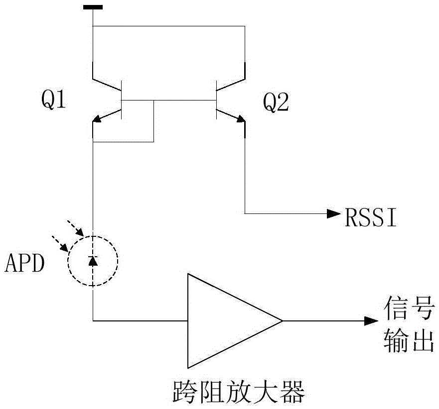
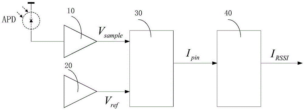
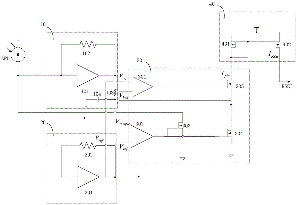
[0028] The present invention is mainly applied to the transimpedance amplifier circuit in optical communication, and is aimed at the key technology of the transimpedance amplifier, that is, the input signal strength display, which is used to accurately display the input signal strength of the avalanche photodiode inside the chip. Therefore, the present invention A new input signal strength display method is designed, and a new circuit structure is proposed. The main principle of the input signal strength display circuit proposed by the present invention is to sample the output voltage signal of the transimpedance amplifier, and the obtained transimpedance The output common-mode DC voltage of the impedance amplifier and the output reference voltage of the virtual transimpedance amplifier are converted to obtain a current signal equivalent to the working current of the avalanche photodiode and output, and then the current signal is amplified according to the current ratio, so that...


PUM


Abstract

The present invention discloses an input signal intensity display circuit for an avalanche photodiode (APD) in a light receive module. The input signal intensity display circuit comprises a transimpedance amplifier output voltage sampling module, a virtual transimpedance amplifier, a transimpedance error amplifier and a current proportion amplifier. The transimpedance amplifier output voltage sampling module is used for sampling an output signal of a transimpedance amplifier so as to obtain an output common mode direct current voltage related to the input signal intensity of the APD. The virtual transimpedance amplifier is used for copying the transimpedance amplifier so as to obtain a circuit the same as the transimpedance amplifier and obtain an output reference voltage when the input signal intensisty is zero. The transimpedance error amplifier is used for converting errors of the output common mode direct current voltage and the output reference voltage, so as to obtain a current signal equivalent to the input current of the APD. The current proportion amplifier is used for performing proportional mirroring on the output current of the transimpedance error amplifier, so as to obtain an input signal intensity display current. According to the input signal intensity display circuit, the input signal intensity of the APD can be displayed inside a chip; a manner of sampling and comparing the output signal of the transimpedance amplifier is adopted, thereby having a small impact on input of the transimpedane amplifier; and peripheral system is simple to use.

Description

technical field [0001] The invention relates to the technical field of optical communication, in particular to an input signal strength display (RSSI, ReceiveSingalStrengthIndicator) circuit used for an APD in an optical receiving module. Background technique [0002] In the field of optical communication, the transimpedance amplifier is usually used as the preamplifier of the receiver, such as figure 1 As shown, it is the schematic diagram of the input signal strength display circuit of the traditional APD (avalanche photodiode), which mainly samples from the negative electrode of the avalanche photodiode, so as to display the amplitude of the input signal outside the chip. The input signal strength is displayed, and this circuit needs to add a pair of mirrored triode circuits in the peripheral application circuit, which makes the peripheral system application complicated. [0003] In view of this, there is an urgent need to provide an input signal strength display circuit...

Claims


Application Information

Patent Timeline
Patent Type & Authority Applications(China)
IPC IPC(8): H04B10/079
CPCH04B10/0795H04B10/0799
Inventor 童志强任娟
Owner FENGHUO COMM SCI & TECH CO LTD
Features
  • R&D
  • Intellectual Property
  • Life Sciences
  • Materials
  • Tech Scout
  • Unparalleled Data Quality
  • Higher Quality Content
  • 60% Fewer Hallucinations
Learn More