
Axle suspension device

A suspension device, axle housing technology, applied in the direction of suspension, elastic suspension, transportation and packaging, etc., to achieve the effect of large height distance and low steering force

Inactive Publication Date: 2016-06-15
ZF FRIEDRICHSHAFEN AG
View PDF5 Cites 3 Cited by
  • Summary
  • Abstract
  • Description
  • Claims
  • Application Information

AI Technical Summary

Problems solved by technology

But therefore the floor height in the vehicle ( ) can only be lowered to the second hinge of the triangular cantilever

Method used


Image

  • Axle suspension device
  • Axle suspension device
  • Axle suspension device

Examples


Embodiment Construction

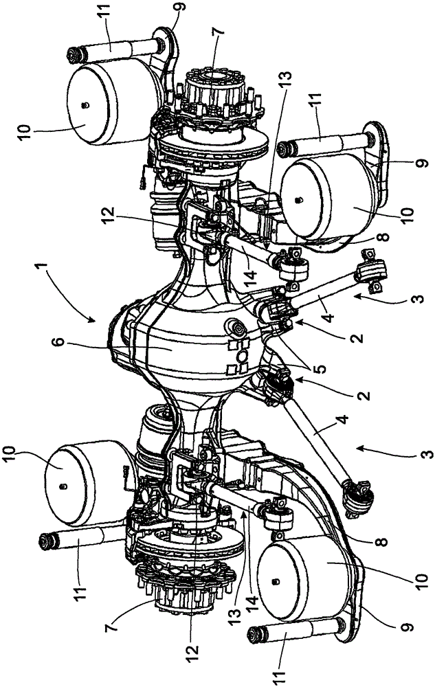
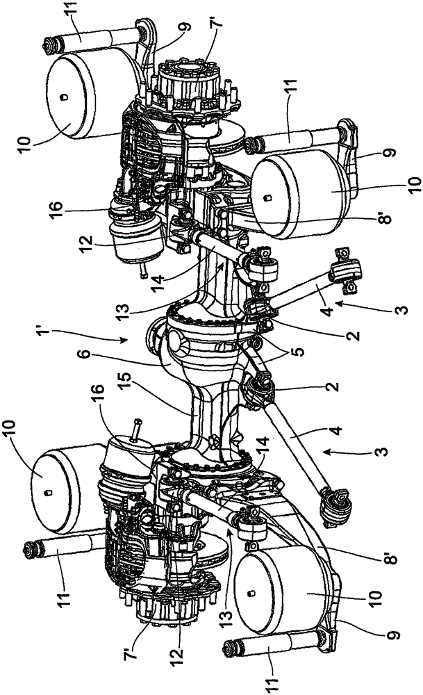
[0022] The illustrated axle suspension of the vehicle generally has an axle housing 1 , 1 ′, 1 ″, 1 ″′ made of metal as a cast part, wherein figure 1 and figure 2 The axle housings 1 and 1' have a transmission housing 6 in the center and are provided for a driven axle. A rotatably mounted wheel drive shaft, not shown, passes through the axle housing 1 , 1 ′, 1 ″, 1 ″′. It goes without saying that, alternatively, the axle housing 1 , 1 ′, 1 ″, 1 ″′ can be formed as a welded structural unit from several parts.

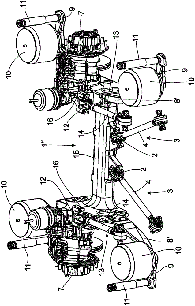
[0023] image 3 and Figure 4 Axle housings 1" and 1"' are provided for non-driven axles and also as figure 2 The portal bridge in.

[0024] In the lower regions of the axle housings 1, 1', 1", and 1"', respectively, two second articulation sites 2 are arranged side by side, at which the triangular cantilever 3 is hinged, and the two stays of the triangular cantilever 4 extends separately from the second articulation point 2 in one plane. The end of the strut 4 ...


PUM


Abstract

The invention relates to an axle suspension device comprising a vehicle axle with an axle housing 1; and at least one vertical suspension arm which extends vertically along the vehicle at each end part region of the vehicle axle and at identical height utilizing hinged at one end of the first hinge portion 12 and axle or axle housing 1 of a connecting member at the other longitudinal end of the cantilever hinged on a frame having a first joint; triangular cantilever 3, which utilizes hinged at one end thereof a second hinge axle located in the center of the two parts 1, two triangular cantilever pull rod 42 extends separately from the first hinge portion 12 at a different height from the second hinge portion in a plane and can use its hinge portion away from the second end portion of the frame 2 is hinged on. The second triangle cantilever hinge portion 3 is disposed below the two vertically uppermost region of the axle housing 1, and a first hinge portion 12 provided in the vertical direction than the second hinge portion 2 higher altitudes.

Description

technical field [0001] The invention relates to a bridge suspension device for a vehicle ( ), comprising: an axle with an axle housing; and at least one longitudinal cantilever extending longitudinally of the vehicle at the same height at each end region of the axle, with one end hinged to or connected to the axle housing At the first hinge position at the part, the other end of the longitudinal suspension has a first joint for being hinged on the vehicle frame; At the second hinged position in the center of the shell, the two pull rods of the triangular cantilever extend separately in a plane from the second hinged position and can be hinged on the vehicle frame by using their ends away from the second hinged position, which is characterized in that , the second hinge portion of the triangular cantilever is disposed below the vertically highest region of the axle housing, and the first hinge portion is disposed at a height higher than the second hinge portion in the vertica...

Claims


Application Information

Patent Timeline
Patent Type & Authority Applications(China)
IPC IPC(8): B60G11/27B60G9/02
CPCB60G9/022B60G11/27B60G2202/1524B60G9/027
Inventor P·伦兹K·阿莱施A·恩德尔D·杜德克P·哈泽尔贝格R·诺伊米勒H·西格尔M·鲍尔D·旺格J·吕夫特尔
Owner ZF FRIEDRICHSHAFEN AG
Learn More