Eureka AIR delivers breakthrough ideas for toughest innovation challenges, trusted by R&D personnel around the world.

A Flapping Rotor Using Openings to Realize Increased Lift

A flapping rotor and wing membrane technology, applied in the field of flapping rotors, can solve the problems of low energy utilization rate and small average lift of flapping rotors, and achieve the effects of increased energy utilization rate, average lift, and easy-to-obtain materials

Active Publication Date: 2017-09-29
BEIHANG UNIV
View PDF7 Cites 0 Cited by
  • Summary
  • Abstract
  • Description
  • Claims
  • Application Information

AI Technical Summary

Problems solved by technology

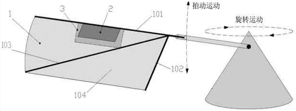
[0005] Aiming at the problem that the average lift of the flapping rotor is small and the energy utilization rate is low due to the negative lift generated by the flapping rotor, the invention proposes a flapping rotor that uses openings to achieve increased lift

Method used


Image

  • A Flapping Rotor Using Openings to Realize Increased Lift
  • A Flapping Rotor Using Openings to Realize Increased Lift
  • A Flapping Rotor Using Openings to Realize Increased Lift

Examples


Embodiment Construction

[0026] The present invention will be further described in detail with reference to the accompanying drawings and embodiments.

[0027] A fluttering rotor that uses openings to increase lift. The working principle is as follows:

[0028] During the use of the micro flapping rotor, the general angle of attack is fixed between 0° and 30°. When the flapping rotor moves upwards, taking the flapping rotor as the reference frame, the flapping motion produces a downward airflow relative to the flapping rotor. After superimposing with the rotating incoming flow, the effective angle of attack formed by the real incoming flow and the flapping rotor is negative. When the pressure on the upper surface of the wing is greater than that on the lower surface, negative lift will be produced on the conventional flapping rotor. When the flapping rotor moves downward, the effective angle of attack formed by the real incoming flow and the flapping rotor is positive. At this time, the pressure on t...


PUM


Abstract

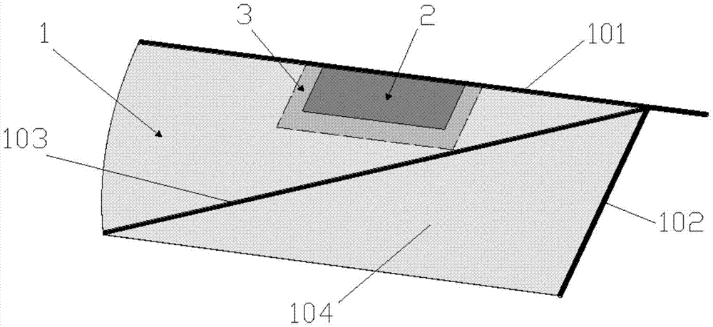
The invention discloses a flapping rotor adopting openings to realize increased lift, which comprises flapping rotors, ventilation holes and hinges; the flapping rotor includes main girders, short beams, inclined beams and wing film; the wing film is glued to the main beam, short beams and inclined beams On the plane formed; the vent hole is a rectangular hole cut out on the wing membrane, and one long side coincides with the front edge of the wing membrane, the hinge is a rectangular resin film, the center coincides with the center of the vent hole, and one long side coincides with the front edge of the wing membrane. The leading edge of the wing is overlapped and bonded to the main spar, and the remaining edge is naturally attached to the membrane; the hinge is located under the membrane and above the beam structure. The advantage is that when the wing moves upward, the hinge opens downward, and the high-pressure airflow on the upper surface of the wing flows to the lower surface through the vent holes, thereby reducing the pressure difference between the upper and lower surfaces of the wing, and realizing the unloading of negative lift; When the wing moves downward, the hinge is attached to the lower surface of the wing, and the airflow cannot pass through the air holes, so the positive lift generated by flapping is maintained, thereby improving the average lift and energy utilization.

Description

technical field [0001] The invention relates to the field of micro-aircraft, in particular to a flapping rotor that adopts openings to realize increased lift. Background technique [0002] Since the 1990s, with the continuous maturity of traditional aircraft design technology and the great progress of microelectronics technology, micro air vehicles have been proposed and developed rapidly. Due to the characteristics of small size, light weight, and strong maneuverability, micro-aircraft has broad application prospects in national security and national economic construction, and is suitable for investigation, exploration, and rescue assistance in complex environments. [0003] At the same time, as people continue to explore the mechanism of natural biological flight and swimming, bionic design is more and more applied to the field of micro air vehicles. The patent application whose publication number is CN 101492093: "Design Method of Flapping Rotor and Micro-miniature Flapp...

Claims


Application Information

Patent Timeline
Patent Type & Authority Patents(China)
IPC IPC(8): B64C33/02
CPCB64C33/02
Inventor 吴江浩陈隆周超
Owner BEIHANG UNIV
Why Eureka
Eureka Blog
Learn More