
A flapping rotor with an angle of attack control device

A control device and a flapping rotor technology, applied in the field of flapping rotors, can solve the problems of low energy utilization rate, small average lift of flapping rotors, etc., and achieve the effects of improved energy utilization rate, improved average lift, and simple design

Active Publication Date: 2016-06-08
BEIHANG UNIV
View PDF8 Cites 0 Cited by
  • Summary
  • Abstract
  • Description
  • Claims
  • Application Information

AI Technical Summary

Problems solved by technology

[0005] The purpose of the present invention is to solve the problem that the average lift of the flapping rotor is small and the energy utilization rate is low due to the negative lift generated by the flapping rotor, and a flapping rotor with an angle of attack control device is proposed.

Method used


Image

  • A flapping rotor with an angle of attack control device
  • A flapping rotor with an angle of attack control device
  • A flapping rotor with an angle of attack control device

Examples


Embodiment 1

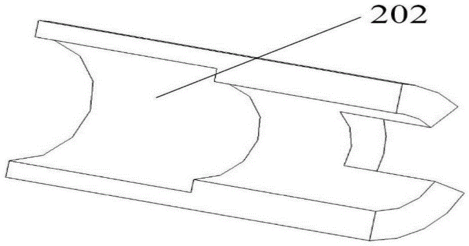
[0033] A flapping rotor with an angle of attack control device includes a flapping rotor 1 , an angle of attack controller 2 and a limiter 3 .

[0034] Flapping rotor 1 such as figure 1 As shown, it includes a main beam 101 , a short beam 102 , an oblique beam 103 , a membrane 104 and a baffle 105 .

[0035] The main beam 101, the short beam 102 and the inclined beam 103 are made of carbon fiber rods, the wing membrane 104 is made of polyethylene film, and the baffle 105 is made of carbon fiber board.

[0036] The main beam 101, the short beam 102, the inclined beam 103 and the baffle 105 are in the same plane, the short beam 102 is perpendicular to the main beam 101, the inclined beam 103 is located between the main beam 101 and the short beam 102, and the included angle with the main beam 101 is 30° to 60°. The root of the short beam 102 and the root of the inclined beam 103 are fixedly connected to the root of the main beam 101 , and the intersection point is located at 1...

Embodiment 2

[0052] A flapping rotor with an angle of attack control device includes: a flapping rotor 1 , a deformation piece 4 and a limit beam 106 .

[0053] Such as Figure 4 As shown, the flapping rotor 1 includes: main beam 101 , short beam 102 , inclined beam 103 and wing membrane 104 . The main beam 101, the short beam 102 and the inclined beam 103 are all made of carbon fiber rods, and the wing membrane 104 is made of polyethylene film.

[0054] The main beam 101 is coplanar with the short beam 102 and the inclined beam 103, the short beam 102 is perpendicular to the main beam 101, the inclined beam 103 is between the main beam 101 and the short beam 102, and the angle between the main beam 101 and the main beam 101 is between 30° and 60° between. The wing membrane 104 is glued below the plane formed by the main beam 101 , the short beam 102 and the inclined beam 103 . The short beam 102 and the oblique beam 103 are fixedly connected at the root, the connection point is about 1...


PUM


Abstract

The invention discloses a flapping rotor with an angle of attack control device, which belongs to the technical field of micro-aircraft. Including flapping rotor, angle of attack control device and limit device; flapping rotor includes main beam, short beam, inclined beam and wing membrane; Stopper and angle of attack controller; a groove is made on the angle of attack controller, and the baffle moves up and down in the groove; the stopper is used to control the range of motion of the baffle. The other includes deformation sheets and limit beams. By changing the thickness of the deformation sheets or adjusting the distance between the connection point of the short beam and the inclined beam and the main beam, the angle of attack of the airfoil when the flapping rotor is shot up is controlled. The limit beam is used to Limit the deformation of the flapping rotor when the flapping rotor is down; by controlling the angle of attack of the flapping rotor during the flapping process, on the basis of maintaining the positive lift, the negative lift is effectively reduced, and the average lift of the micro flapping rotor aircraft is improved. The energy utilization rate of the aircraft is improved.

Description

technical field [0001] The invention relates to the field of micro-aircraft, in particular to a flapping rotor with an angle of attack control device. Background technique [0002] Since the 1990s, with the continuous improvement of traditional aircraft design technology, people have continued to explore and understand the mechanism of animal flight and swimming, and with the rapid development of microelectronics technology, the field of micro air vehicle design It is developing more and more rapidly, and has broad application prospects in national security and national economic construction. It is applied to tasks such as reconnaissance, communication, exploration, and assistance in rescue under complex environmental conditions. [0003] Publication number is the patent application of CN101492093: " flapping rotor design method and the miniature flapping rotor aircraft designed by this method " discloses miniature flapping rotor aircraft. The lift of the micro flapping rot...

Claims


Application Information

Patent Timeline
Patent Type & Authority Patents(China)
IPC IPC(8): B64C33/02
Inventor 吴江浩周超张艳来
Owner BEIHANG UNIV
Learn More