Stamping die suspension mechanism

A technology of stamping dies and guide tubes, which is applied to portable lifting devices, hoisting devices, etc., can solve the problems of inconvenient installation, low handling efficiency, and inconvenient vertical lifting and handling, and achieve convenient handling and vertical lifting and moving , The effect of convenient and firm installation

Inactive Publication Date: 2016-06-15
SUZHOU HEYER PRECISION CO LTD
View PDF8 Cites 1 Cited by
  • Summary
  • Abstract
  • Description
  • Claims
  • Application Information

AI Technical Summary

Problems solved by technology

The stamping die is inconvenient to realize vertical lifting and transportation, and the transportation efficiency is low, so it is not convenient to install on the stamping machine tool

Method used


Image

  • Stamping die suspension mechanism

Examples


Embodiment Construction

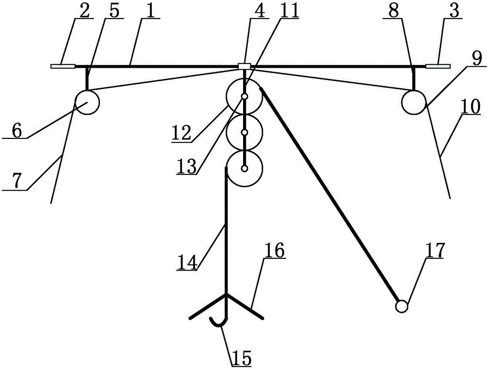
[0012] In order to make the technical means, creative features, goals and effects achieved by the present invention easy to understand, the present invention will be further described below in conjunction with specific embodiments.

[0013] Such as figure 1 As shown, a suspension mechanism for a stamping die includes a guide tube 1, one end of the guide tube 1 is provided with a first installation piece 2, the first installation piece 2 is arranged horizontally, and the other end of the guide tube 1 is provided with a second installation piece 3. The second mounting piece 3 is arranged horizontally; the outer peripheral surface of the guide tube 1 is covered with a moving tube 4, and the moving tube 4 is vertically arranged; The lower end of the first guide wheel 6 is provided with the first guide wheel 6, the first guide wheel 6 is surrounded by the first slide fastener 7, one end of the first slide fastener 7 is a free end, the other end of the first slide fastener 7 is conn...


PUM


Abstract

The invention discloses a suspension mechanism of a stamping die, which comprises a guide tube, a moving tube is set on the outer peripheral surface of the guide tube, an installation rod is arranged at the lower part of one end of the guide tube, and a guide wheel is arranged at the lower end of the installation rod, and a zipper is wound around the guide wheel , one end of the zipper is a free end, the other end of the zipper is connected to the moving tube, the lower part of the moving tube is provided with a moving rod, and a fixed pulley is arranged on the moving rod, and the fixed pulley is composed of several guide wheels connected; the fixed pulley is wound with a lifting chain, One end of the lifting chain is a free end, and the other end of the lifting chain is provided with a locking hook. The invention realizes pulling along the fixed pulley through the lifting chain, so as to facilitate the vertical lifting and moving of the stamping die and the transportation of the stamping die.

Description

technical field [0001] The invention relates to a suspension mechanism, in particular to a stamping die suspension mechanism. Background technique [0002] In the prior art, patent ZL200910213867.4 discloses an IC stamping die, which consists of a lower die base, a lower die body, a stripper plate, a punch fixing plate, a punch backing plate, an upper die base, an outer guide column, a suspension Hanging mechanism, spring seat, punch, stop block, outer guide sleeve, inner guide column, positioning device, stripping plate input block, floating material pin, knife edge input block, material guide plate, inner guide sleeve, its characteristics The lower mold is composed of knife edge, material guide plate, floating material pin, lower mold body, lower mold base, stop block, inner and outer guide sleeves. The lower mold body is installed on the lower mold base, and the material guide plate is installed on the lower mold body. , the inner guide sleeve is set on the lower die bas...

Claims


Application Information

Patent Timeline
Patent Type & Authority Applications(China)
IPC IPC(8): B66D3/06
CPCB66D3/06B66D2700/026
Inventor 黄文卿
Owner SUZHOU HEYER PRECISION CO LTD
Why Eureka
Try Eureka