Backlight module and display device

A backlight module and backplane technology, which is applied to lighting devices, fixed lighting devices, components of lighting devices, etc., can solve problems such as bulging deformation, wrinkling, and image quality effects on the upper or lower ends of the light board.

Inactive Publication Date: 2016-06-15
BOE TECH GRP CO LTD +1
View PDF16 Cites 8 Cited by
  • Summary
  • Abstract
  • Description
  • Claims
  • Application Information

AI Technical Summary

Problems solved by technology

[0003] However, there are some difficulties in setting the gap value. If the gap between the light guide plate and the limiting structure is set larger, then after the assembly is completed or in the subsequent transportation process, if the light guide plate is affected by vibration, the light guide plate will be in the There is a large displacement at the gap, which will cause strong friction with the reflective layer under the light guide plate and the diffusion layer above, causing poor white spots, which will affect the screen display
If the gap is set too small, the thermal expansion of the light guide plate may exceed the initial d

Method used


Image

  • Backlight module and display device
  • Backlight module and display device
  • Backlight module and display device

Examples


Embodiment Construction

[0043] In order to understand the above-mentioned purpose, features and advantages of the present invention more clearly, the present invention will be further described in detail below in conjunction with the accompanying drawings and specific embodiments. It should be noted that, in the case of no conflict, the embodiments of the present application and the features in the embodiments can be combined with each other.

[0044] In the following description, many specific details are set forth in order to fully understand the present invention. However, the present invention can also be implemented in other ways different from those described here. Therefore, the protection scope of the present invention is not limited by the specific details disclosed below. EXAMPLE LIMITATIONS.

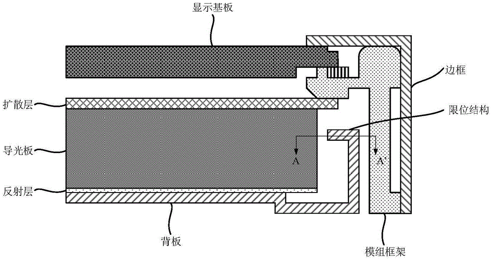
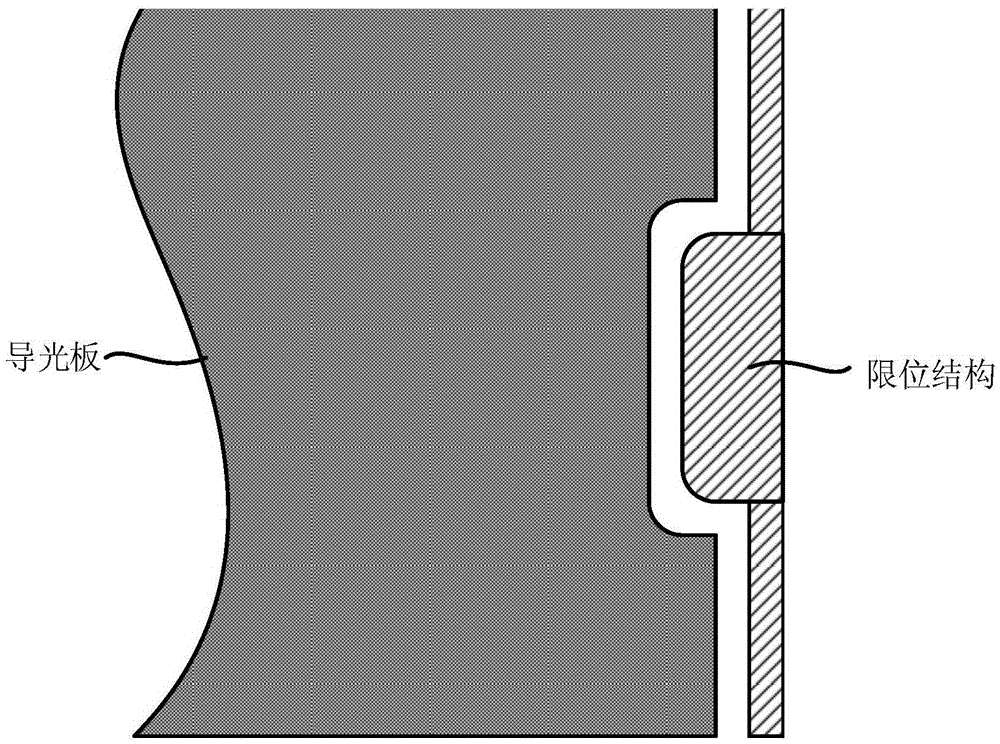
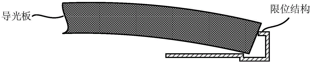
[0045] like Figure 4 to Figure 6 As shown, the backlight module according to an embodiment of the present invention includes a light guide plate 3 and a limiting structure 10, and the limiting stru...


PUM


Abstract

The invention relates to a backlight module which comprises a light guide plate and a limiting structure. The limiting structure comprises a supporting plate and an elastic limiting protrusion arranged on the supporting plate. The elastic limiting protrusion corresponds to the side face of the light guide plate and is deformed in the direction perpendicular to the supporting plate when being pressed by pressure from the side face of the light guide plate. By means of the technical scheme, when the light guide plate vibrates or expands, pressure is produced on the elastic limiting protrusion, and the light guide plate does not make direct contact with the supporting face. On the one hand, a light guide plate limiting function is guaranteed, so that the phenomenon that displacement of the light guide plate is too large, and the white dot defect is caused by friction of the light guide plate and a reflecting layer and/or a diffusion layer is avoided; on the other hand, the problem that the deformation defect is caused due to the fact that the light guide plate protrudes upwards or downwards because of over-high resistance of the supporting plate when the light guide plate moves is solved.

Description

technical field [0001] The present invention relates to the field of display technology, in particular, to a backlight module and a display device. Background technique [0002] The structure of the existing backlight module is as follows figure 1 and figure 2 As shown in the figure, it includes sequentially setting a reflective layer, a light guide plate, a diffusion layer and other structures on the backplane, a module frame is also set on the backlight module, the display substrate is set on the module frame, and finally the frame is assembled to form a display The prototype of the panel. In this structure, in order to facilitate the assembly of related parts, a certain gap is left between the structures (such as the light guide plate and the limiting structure), and for the light guide plate that is sensitive to surrounding changes such as temperature and humidity, in order to ensure a certain temperature and humidity reliability The gap value can be set according to...

Claims


Application Information

Patent Timeline
IPC IPC(8): F21S8/00F21V17/16
CPCF21S8/00F21V17/16G02B6/0051G02B6/0088G02F1/133615G02F2201/54G02B6/00G02F1/133322
Inventor 李相稙
Owner BOE TECH GRP CO LTD
Why Eureka
Try Eureka