
Main-auxiliary type multi-heat-source series-connection grid-connected heating device

A heating device and multi-heat source technology, applied in the directions of household heating, heating system, space heating and ventilation, etc., can solve the problems of disconnection from the Internet, waste of heat source resources and human resources, no peak regulation, and backup functions.

Inactive Publication Date: 2016-06-15
XINJIANG NORTH TIANHENG ENERGY SAVING TECH CO LTD
View PDF5 Cites 4 Cited by
  • Summary
  • Abstract
  • Description
  • Claims
  • Application Information

AI Technical Summary

Problems solved by technology

[0003] The present invention provides a primary and auxiliary multi-heat source series-connected grid-connected heating device, which overcomes the above-mentioned deficiencies in the prior art, and can effectively solve the problem that the new and old boiler rooms in the existing central heating system operate independently and are not connected to the Internet. No peak shaving and backup functions, great waste of heat source resources and human resources, unable to meet energy conservation and environmental protection requirements

Method used


Image

  • Main-auxiliary type multi-heat-source series-connection grid-connected heating device
  • Main-auxiliary type multi-heat-source series-connection grid-connected heating device
  • Main-auxiliary type multi-heat-source series-connection grid-connected heating device

Examples


Embodiment 1

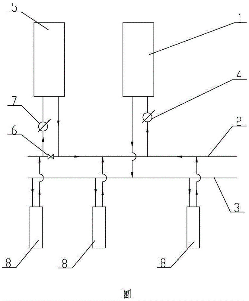
[0021] Embodiment one: as attached figure 1As shown, in this embodiment, the main and auxiliary multi-heat source series grid-connected heating device includes a main heat source 1 and an auxiliary heat source 5, a check valve 6 is provided on the primary return line 2, and the water inlet of the auxiliary heat source 5 The water outlet of the auxiliary heat source 5 is communicated with the primary return line 2 on the right side of the one-way valve 6 through the pipeline; the water inlet of the main heat source 1 is connected with the single It is connected to the primary return water line 2 on the right side of the valve 6; the water outlet of the main heat source 1 is connected to the primary water supply line 3 through a pipe; An auxiliary circulation pump 7 is provided on the pipeline; a main circulation pump 4 is provided on the pipeline between the water inlet of the main heat source 1 and the primary return water pipeline 2 on the right side of the one-way valve 6 . ...

Embodiment 2

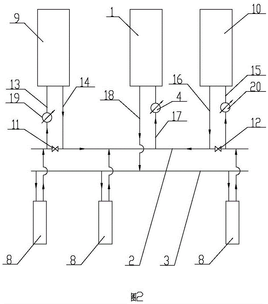
[0026] Embodiment two: as attached figure 2 As shown, this embodiment is basically the same as Embodiment 1, the difference is that the main and auxiliary multi-heat source series grid-connected heating device includes the main heat source 1, the first auxiliary heat source 9 and the second auxiliary heat source 10, and the primary return water The pipeline 2 is provided with a first one-way valve 11 and a second one-way valve 12 in sequence from left to right. The water pipeline 2 communicates, and the water outlet of the first auxiliary heat source 9 communicates with the primary return water pipeline 2 on the right side of the first one-way valve 11 through the second pipeline 14; the water inlet of the second auxiliary heat source 10 communicates with the water inlet through the third pipeline 15. The primary return line 2 located on the right side of the second check valve 12 communicates, and the water outlet of the second auxiliary heat source 10 communicates with the ...

Embodiment 3

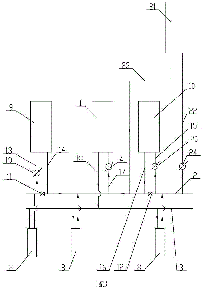
[0027] Embodiment three: as attached image 3 As shown, this embodiment is basically the same as Embodiment 2, the difference is that the main and auxiliary multi-heat source series grid-connected heating device includes a main heat source 1, a first auxiliary heat source 9, a second auxiliary heat source 10 and a third auxiliary heat source The heat source 21 and the primary return water line 2 are provided with a first one-way valve 11 and a second one-way valve 12 in sequence from left to right, and the water inlet of the first auxiliary heat source 9 is connected to the The primary return line 2 on the left side of 11 is connected, and the water outlet of the first auxiliary heat source 9 is connected with the primary return line 2 on the right side of the first one-way valve 11 through the second pipe 14; the water inlet of the second auxiliary heat source 10 The third pipe 15 communicates with the primary return line 2 on the right side of the second one-way valve 12 , a...


PUM


Abstract

The invention relates to the technical field of heating devices, in particular to a main-auxiliary type multi-heat-source series-connection grid-connected heating device. The main-auxiliary type multi-heat-source series-connection grid-connected heating device comprises a main heat source and at least one auxiliary heat source. One-way valves are arranged on a primary water return pipeline. Water inlets of the auxiliary heat sources communicate with the parts, on the outer sides of the one-way valves, of the primary water return pipeline. Water outlets of the auxiliary heat sources communicate with the parts, on the inner sides of the one-way valves, of the primary water return pipeline. A water inlet of the main heat source communicates with the part, on the inner sides of the one-way valves, of the primary water return pipeline. A water outlet of the main heat source communicates with a primary water supply pipeline. Auxiliary circulating pumps are arranged on pipelines between the water inlets of the auxiliary heat sources and the parts, on the outer sides of the one-way valves, of the primary water return pipeline. A main circulating pump is arranged on a pipeline between the water inlet of the main heat source and the part, on the inner sides of the one-way valves, of the primary water return pipeline. According to the main-auxiliary type multi-heat-source series-connection grid-connected heating device, the multiple heat sources are connected to a grid in series, the auxiliary heat sources only heat one side of the primary water return pipeline, a boiler is started and stopped according to the system heat requirement, the heat power of the boiler is fully used, and the purposes of regulating the peak, achieving standby application and increasing the utilization rate of the heat sources are realized.

Description

technical field [0001] The invention relates to the technical field of heating devices, and relates to a primary and auxiliary multi-heat source series-connected grid-connected heating device. Background technique [0002] Due to the low temperature in winter in cities and towns in northern my country, central heating is generally used in winter. In order to avoid large horse-drawn carts in the boiler room during the initial construction, resulting in waste of energy consumption, the installed capacity of the designed heat source is basically based on the existing building area plus the reserved planning margin. With the rapid development of the country's urbanization construction, the load of the original boiler room can no longer meet the demand, so a new boiler room can only be built. Restricted by the site, region, and environmental protection, it is generally chosen to build a new boiler room with a large installed capacity next to the original site, or to build a boil...

Claims


Application Information

Patent Timeline
Patent Type & Authority Applications(China)
IPC IPC(8): F24D12/02
CPCY02B30/00
Inventor 李微毛建涛
Owner XINJIANG NORTH TIANHENG ENERGY SAVING TECH CO LTD
Learn More