Underwear cotton cup forming device
A molding device and cotton cup technology, which is applied in the direction of household components, household appliances, and other household appliances, can solve the problems of low molding efficiency and high labor costs, and achieve the effects of improving molding efficiency, reducing labor costs, and reducing labor usage.
- Summary
- Abstract
- Description
- Claims
- Application Information
AI Technical Summary
Problems solved by technology
Method used
Image
Examples
Embodiment 1
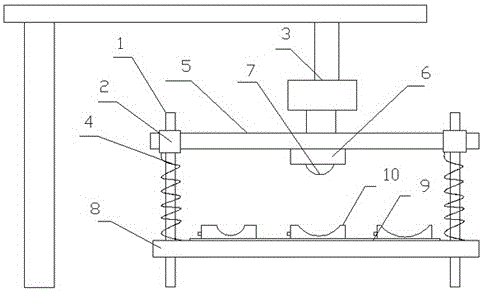
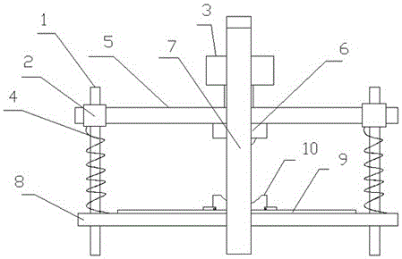
[0023] This embodiment includes upper mold, lower mold, guide rod 1, guide sleeve 2, depressing cylinder 3 and return spring 4, described upper mold includes upper mold base 5, upper template 6 and forming punch 7, and upper template 6 is installed On the upper mold base 5, the molding punch 7 is fixed on the upper template 6, and the lower mold includes the lower mold base 8, the lower template 9 and the forming die 10, the lower template 9 is installed on the lower mold base 8, and the forming die 10 is installed on the lower template 9, the guide rod 1 is fixed on the lower mold base 8, the return spring 4 is sleeved on the guide rod 1, a guide sleeve 2 is installed on the upper mold base 5, and the guide rod 1 passes through Guide sleeve 2, back-moving spring 4 are limited between guide sleeve 2 and lower mold base 8, and depressing cylinder 3 is fixed on the upper mold base 5, and depressing cylinder 3 promotes upper mold base 5 to press down. Press down the cylinder to p...
Embodiment 2
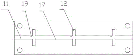
[0025] This embodiment includes upper mold, lower mold, guide rod 1, guide sleeve 2, depressing cylinder 3 and return spring 4, described upper mold includes upper mold base 5, upper template 6 and forming punch 7, and upper template 6 is installed On the upper mold base 5, the molding punch 7 is fixed on the upper template 6, and the lower mold includes the lower mold base 8, the lower template 9 and the forming die 10, the lower template 9 is installed on the lower mold base 8, and the forming die 10 is installed on the lower template 9, the guide rod 1 is fixed on the lower mold base 8, the return spring 4 is sleeved on the guide rod 1, a guide sleeve 2 is installed on the upper mold base 5, and the guide rod 1 passes through Guide sleeve 2, back-moving spring 4 are limited between guide sleeve 2 and lower mold base 8, and depressing cylinder 3 is fixed on the upper mold base 5, and depressing cylinder 3 promotes upper mold base 5 to press down. Press down the cylinder to p...
Embodiment 3
[0028] This embodiment includes upper mold, lower mold, guide rod 1, guide sleeve 2, depressing cylinder 3 and return spring 4, described upper mold includes upper mold base 5, upper template 6 and forming punch 7, and upper template 6 is installed On the upper mold base 5, the molding punch 7 is fixed on the upper template 6, and the lower mold includes the lower mold base 8, the lower template 9 and the forming die 10, the lower template 9 is installed on the lower mold base 8, and the forming die 10 is installed on the lower template 9, the guide rod 1 is fixed on the lower mold base 8, the return spring 4 is sleeved on the guide rod 1, a guide sleeve 2 is installed on the upper mold base 5, and the guide rod 1 passes through Guide sleeve 2, back-moving spring 4 are limited between guide sleeve 2 and lower mold base 8, and depressing cylinder 3 is fixed on the upper mold base 5, and depressing cylinder 3 promotes upper mold base 5 to press down. Press down the cylinder to p...
PUM
 Abstract
Description
Claims
Application Information
 - R&D
- Intellectual Property
- Life Sciences
- Materials
- Tech Scout
- Unparalleled Data Quality
- Higher Quality Content
- 60% Fewer Hallucinations
Browse by: Latest US Patents, China's latest patents, Technical Efficacy Thesaurus, Application Domain, Technology Topic, Popular Technical Reports.
© 2025 PatSnap. All rights reserved.Legal|Privacy policy|Modern Slavery Act Transparency Statement|Sitemap|About US| Contact US: help@patsnap.com


