Rotor device for vacuum pump and method of manufacturing the same

A technology for vacuum pumps and rotors, which is applied to parts, pumps, axial flow pumps, etc. of pumping devices for elastic fluids. It can solve the problems of reduced joint force and improve performance.

Active Publication Date: 2019-10-18
PFEIFFER VACUUM GMBH
View PDF6 Cites 0 Cited by
  • Summary
  • Abstract
  • Description
  • Claims
  • Application Information

AI Technical Summary

Problems solved by technology

The joint force may also be reduced due to temperature effects

Method used


Image

  • Rotor device for vacuum pump and method of manufacturing the same
  • Rotor device for vacuum pump and method of manufacturing the same
  • Rotor device for vacuum pump and method of manufacturing the same

Examples


Embodiment Construction

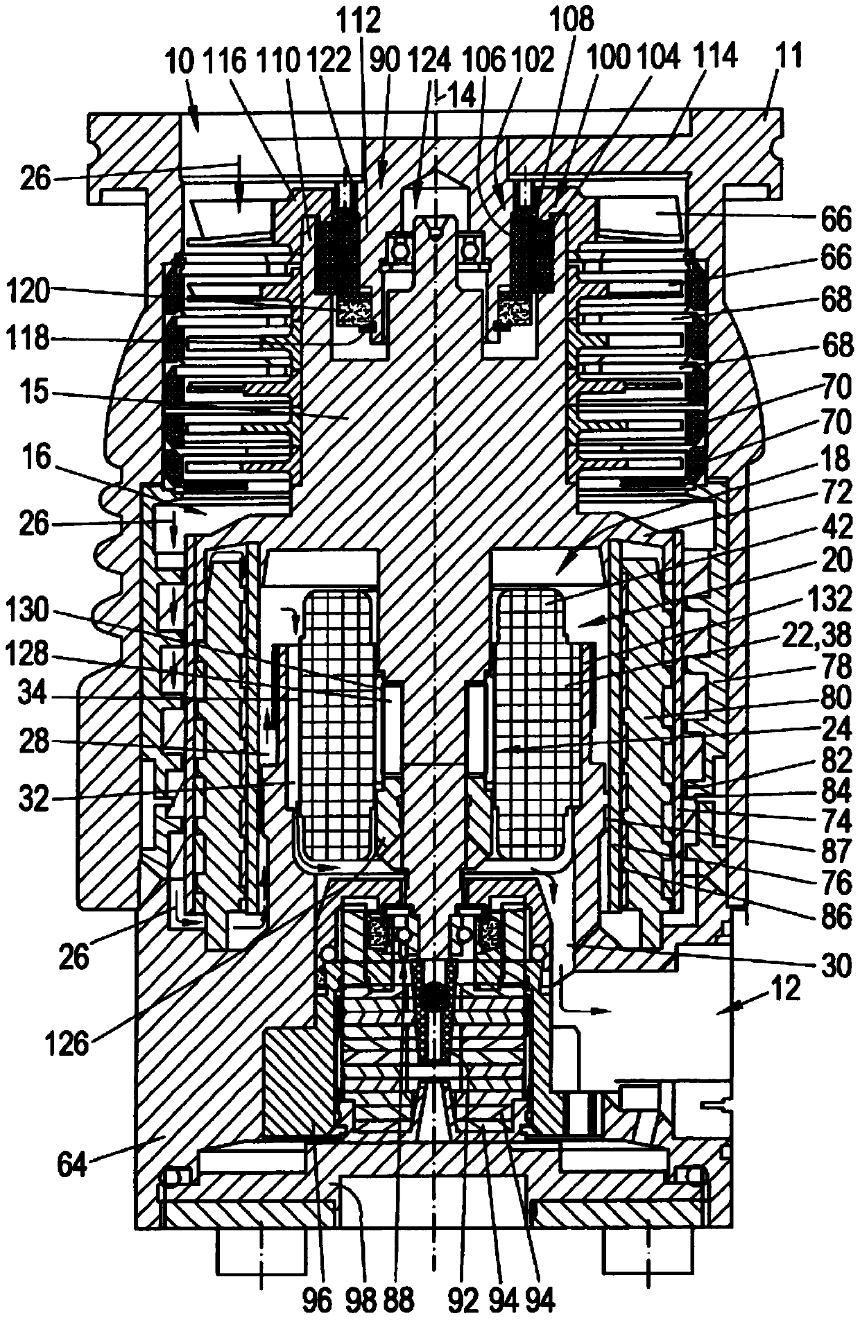
[0114] figure 1 The vacuum pump shown in includes a pump inlet 10 surrounded by an inlet flange 11 , a pump outlet 12 and a plurality of process gas pump steps for conveying process gas at the pump inlet 10 to the pump outlet 12 . The vacuum pump comprises a housing 64 and a rotor 16 arranged in the housing 64 , which has a rotor shaft 15 mounted rotatably about an axis of rotation 14 .

[0115]In the present exemplary embodiment, the pump is designed as a turbomolecular pump and comprises a plurality of turbomolecular pump stages connected in series with each other in a pumping manner (pumpwirksam), which have a plurality of radial pump stages fastened to the rotor shaft 15 . The rotor disk 66 and the stator disk 68 arranged in the middle of the rotor disk 66 and fixed in the housing 64, wherein the rotor disk 66 and the adjacent stator disk 68 respectively form a turbomolecular pump stage. The stator disks 68 are kept at the desired axial distance from one another by spacer...


PUM


Abstract

The invention relates to a rotor assembly for a vacuum pump and especially for a turbomolecular pump. The rotor assembly comprises a rotor shaft and at least on rotor disk. The rotor disk comprises an accomodating opening for accomodating the center of the rotor shaft. The rotor disk is arranged on the rotor shaft. A mechanical connection is built between the rotor disk and the rotor shaft. The rotor assembly is characterized in that mechanical connection is achieved through a heat joint method.

Description

technical field [0001] The invention relates to a rotor arrangement and a method for producing a rotor arrangement. Background technique [0002] Vacuum pumps, such as turbomolecular pumps, are used in various technical fields in order to provide the vacuum required for the respective process. A turbomolecular pump typically includes a rotor shaft, a plurality of rotor disks connected to the rotor shaft, and stator disks arranged between the rotor disks. In this case, the rotor disk and the stator disk each have blades, which are also referred to as vanes. The paddles form a pumpaktiv structure and create the desired pumping action when the rotor arrangement turns rapidly relative to the stator arrangement. [0003] It is known from the prior art that the rotor arrangement of a turbomolecular pump is cut from a single component or is joined together from a plurality of individual rotor disks. In this case, the one-piece production is very time-consuming and production-int...

Claims


Application Information

Patent Timeline
Patent Type & Authority Patents(China)
IPC IPC(8): F04D19/04F04D29/32
CPCF04D19/042F04D29/32F04D29/266F04D29/321F04D29/644
Inventor 弗洛里安·巴德阿明·康拉德马蒂亚斯·马德勒米尔科·马科塔
Owner PFEIFFER VACUUM GMBH
Why Eureka
Try Eureka