Connecting lock

A technology of connecting locks and shackles, which is applied in the field of connecting locks, can solve problems such as inability to maintain, unfavorable installation and transportation, and achieve the effect of convenient installation and transportation

Active Publication Date: 2016-06-22
ROE VISUAL CO LTD
View PDF6 Cites 3 Cited by
  • Summary
  • Abstract
  • Description
  • Claims
  • Application Information

AI Technical Summary

Problems solved by technology

The main disadvantage of this structure is that, since the pull lock is only pivotally connected to the handle, when the pull lock is adjusted to an angular position, the pull lock cannot maintain that angular position. , and will swing when there is a slight shake, which is not conducive to installation and transportation

Method used


Image

  • Connecting lock
  • Connecting lock
  • Connecting lock

Examples


Embodiment Construction

[0018] In order to describe the technical content, structural features, achieved goals and effects of the present invention in detail, the following will be described in detail in conjunction with the embodiments and accompanying drawings.
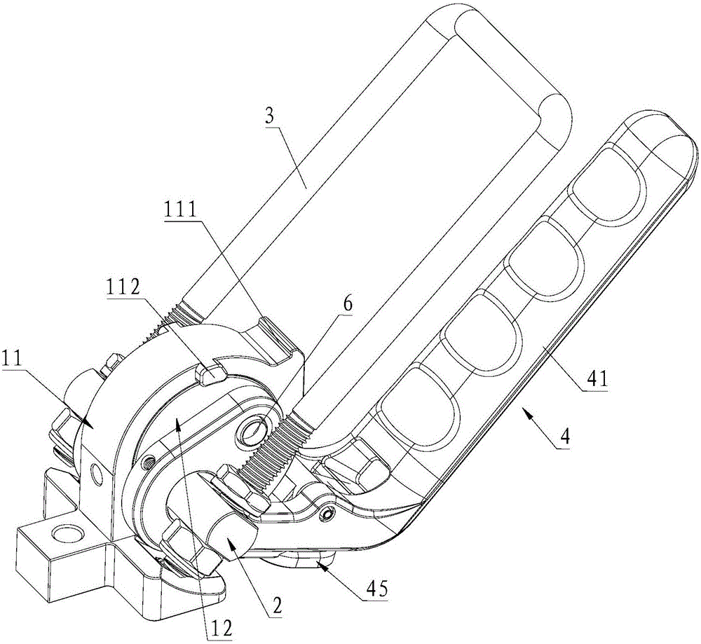
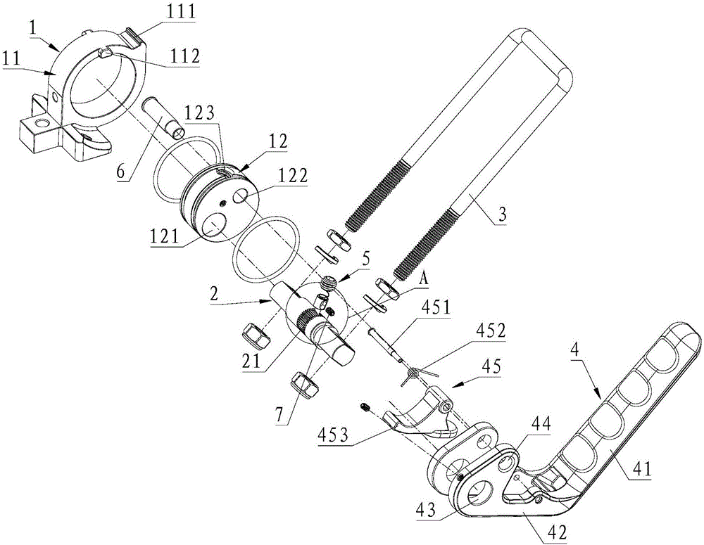
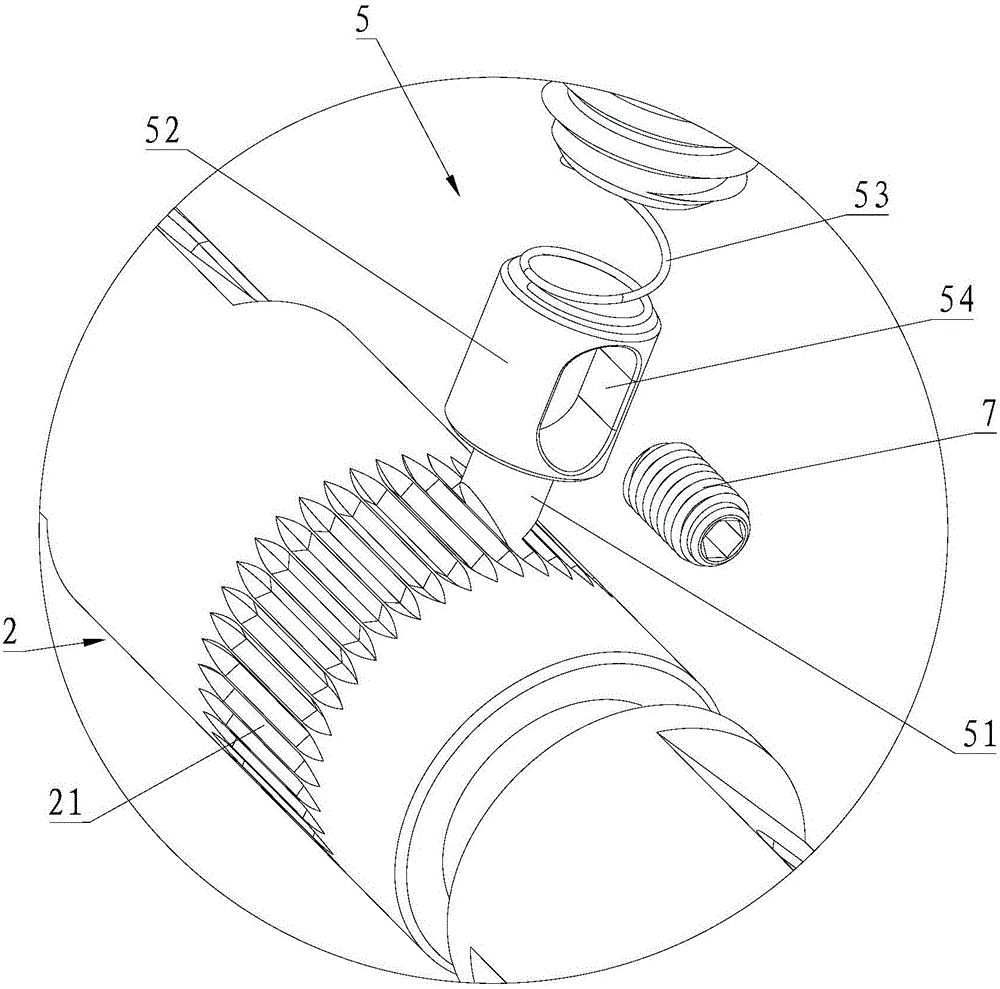
[0019] The most critical idea of ​​the present invention is: the first shaft hole 121 is provided on the base 1 of the present invention, and the inner wall surface of the first shaft hole 121 is provided with a telescopic tongue 5, the first shaft 2 is provided with a plurality of teeth 21 and the first shaft 2 is installed in the shaft hole, and the present invention can effectively maintain the positioning of the lock hook 3 according to the specific angle of rotation.

[0020] see Figure 1 to Figure 4 , the connection lock of the present invention includes a base 1, a first rotating shaft 2 and a locking hook 3, the locking hook 3 is connected to the first rotating shaft 2, a first shaft hole 121 is provided on the base 1, and the fir...


PUM


Abstract

The invention discloses a connecting lock which comprises a base, a first rotary shaft and a lock hook. The lock hook is connected to the first rotary shaft. The base is provided with a first shaft hole. A stretching tongue part is arranged on the inner wall of the first shaft hole. A plurality of teeth are arranged in the circumferential direction of the first rotary shaft. The first rotary shaft is arranged in the first shaft hole in a penetrating mode, and the teeth are matched with the stretching tongue part. According to the connecting lock, the lock hook can be kept in the position of the specific rotation angle, and the lock hook does not swing even under slight shaking as the protruding teeth are arranged on the two sides of the stretching tongue part, so that the connecting lock is convenient to assemble and transport.

Description

technical field [0001] The invention relates to the field of fixed connection devices, in particular to a connection lock. Background technique [0002] The LED display screen is spliced ​​by multiple LED cabinets. Due to the heavy weight of the LED cabinets, connection locks are usually used to splice multiple LED cabinets together. [0003] At present, the splicing between the LED cabinets is generally connected and locked by a locking device with high strength. The locking device on the market generally includes a metal fixing piece and screws, and the two ends of the metal piece are respectively fixed by screws. Two adjacent LED boxes, so as to achieve the purpose of fixed connection. However, this connection method of the LED box is time-consuming and laborious in the actual operation process, and the efficiency is low. [0004] The application number is 201410155096.9, and the Chinese patent titled the lock mechanism discloses a lock used for connecting the display b...

Claims


Application Information

Patent Timeline
Patent Type & Authority Applications(China)
IPC IPC(8): F16B1/02
CPCF16B1/02
Inventor 蔡丹虎李展强张洪蒋旭华
Owner ROE VISUAL CO LTD
Why Eureka
Try Eureka