Check patentability & draft patents in minutes with Patsnap Eureka AI!

Two-dimensional position optical measurement system based on multi-linear-array CCD parallel splicing

An optical measurement system and two-dimensional position technology, applied in the field of optical measurement, can solve the problem of expensive optical system and achieve the effect of ensuring measurement accuracy

Active Publication Date: 2016-06-22
XI'AN INST OF OPTICS & FINE MECHANICS - CHINESE ACAD OF SCI
View PDF7 Cites 3 Cited by
  • Summary
  • Abstract
  • Description
  • Claims
  • Application Information

AI Technical Summary

Problems solved by technology

[0002] Due to the large number of single-dimensional pixels of the area array CCD, the area array CCD is often used for measurement in the two-dimensional position measurement with high precision and large range, but the price of this optical system is relatively expensive.

Method used


Image

  • Two-dimensional position optical measurement system based on multi-linear-array CCD parallel splicing
  • Two-dimensional position optical measurement system based on multi-linear-array CCD parallel splicing
  • Two-dimensional position optical measurement system based on multi-linear-array CCD parallel splicing

Examples


Embodiment Construction

[0026] The present invention will be further described below in conjunction with the accompanying drawings and specific embodiments.

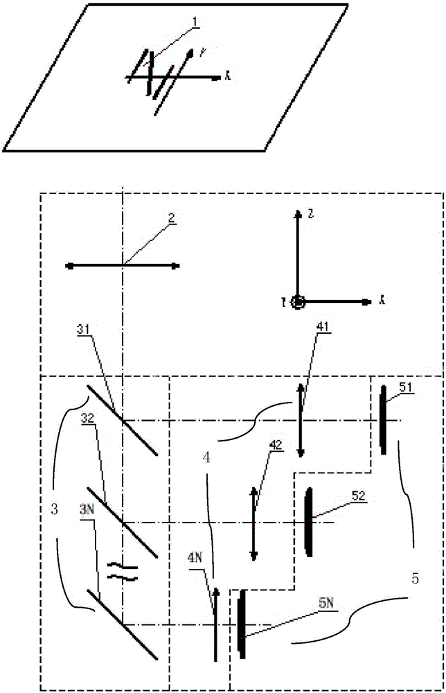
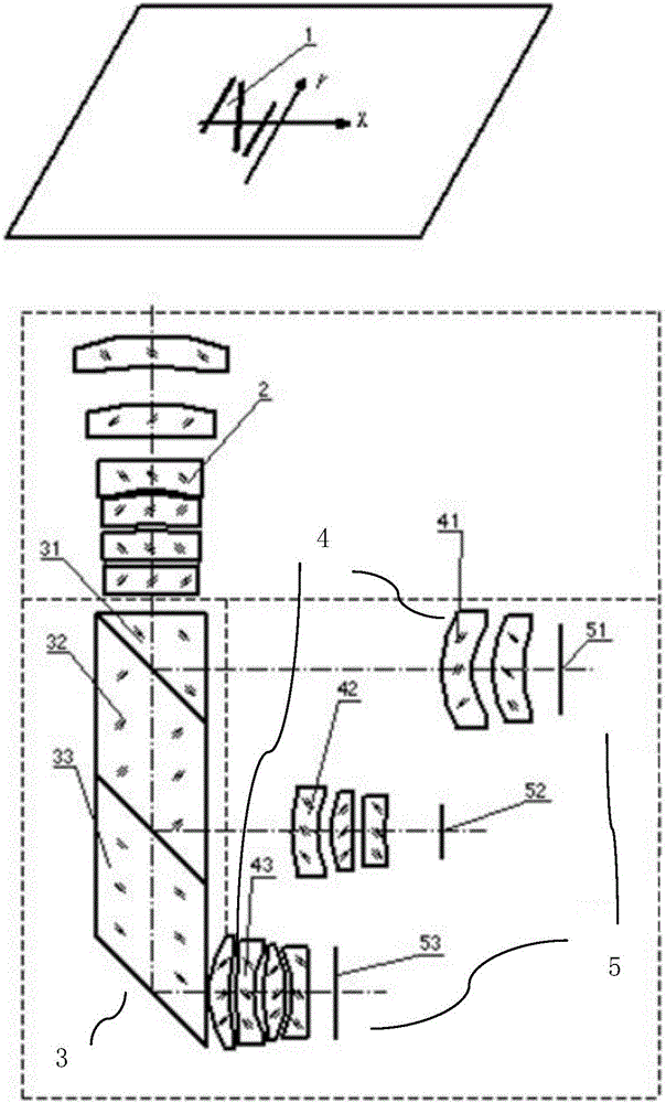
[0027] Such as figure 1 As shown, the two-dimensional position optical measurement system based on multi-linear array CCD parallel splicing provided by the present invention includes a light source cooperative target 1, a common objective lens 2, a beam splitter group 3, a field lens group 4 and a linear CCD group 5.

[0028] The common objective lens 2 is used to collect light beams of various fields of view, the beam splitter group 3 is used to split the light beams, and the field lens group 4 is used to correct the optical path difference of the beams of different fields of view after splitting.

[0029] The light source cooperation target 1 is composed of laser or LED light source or other lighting sources to illuminate the reticle through the uniform light system. In order to reduce the loss of light energy in the measurement process, a wi...


PUM


Abstract

The invention provides a two-dimensional position optical measurement system based on multi-linear-array CCD parallel splicing. The system is composed of a light source cooperative target, a shared objective lens, a light splitter lens group and a linear array CCD group. The light splitter lens group includes a plurality of light splitters arranged on an output path of the shared objective lens successively. The linear array CCD group includes a plurality of linear-array CCDs corresponding to the light splitters one by one; the linear-array CCDs and the light source cooperative target conjugate respectively by the respective light paths; a photosensitive surface of each linear-array CCD is located at a YOZ plane of a rectangular coordinate system and a photosensitive length direction is parallel to an OZ axis. During measurement, a to-be-measured object is fixedly connected with the light source cooperative target; the light source cooperative target carries out imaging on the linear array CCD group by the shared objective lens and light splitter lens group; and two-dimensional position measurement of the light source cooperative target is completed jointly by a first linear-array CCD, a second linear-array CCD, a third linear-array CCD, ... , and an Nth linear-array CCD. The provided system has advantages of low cost and high precision.

Description

technical field [0001] The invention belongs to the technical field of optical measurement, and designs a two-dimensional position optical measurement system based on multi-line array CCD parallel splicing. Background technique [0002] Due to the large number of single-dimensional pixels of the area array CCD, the area array CCD is often used for measurement in the two-dimensional position measurement with high precision and large range, but the price of this optical system is relatively expensive. Compared with the area array CCD, the price of the line array CCD is relatively low, and the number of one-dimensional pixels can be made a lot, while the total number of pixels is less than that of the area array CCD, the pixel size is more flexible, and the frame rate per second is high. , so the linear array CCD is often used for position measurement of one-dimensional dynamic targets. Contents of the invention [0003] The technical problem to be solved by the present inve...

Claims


Application Information

Patent Timeline
IPC IPC(8): G01B11/00
CPCG01B11/00
Inventor 刘爱敏肖茂森高立民陆卫国王海霞贾乃勋
Owner XI'AN INST OF OPTICS & FINE MECHANICS - CHINESE ACAD OF SCI
Features
  • R&D
  • Intellectual Property
  • Life Sciences
  • Materials
  • Tech Scout
  • Unparalleled Data Quality
  • Higher Quality Content
  • 60% Fewer Hallucinations
Learn More