Wave-front defocus correction device

A technology of wavefront defocus correction and cooling cavity, which is applied in the direction of optical components, optics, instruments, etc., can solve the problems of defocus aberration, poor beam quality, difficulty in improving energy concentration, etc. Effects of avoiding additional aberrations and avoiding out-of-focus aberrations

Inactive Publication Date: 2016-06-22
INST OF APPLIED ELECTRONICS CHINA ACAD OF ENG PHYSICS
View PDF4 Cites 6 Cited by
  • Summary
  • Abstract
  • Description
  • Claims
  • Application Information

AI Technical Summary

Problems solved by technology

During the loading process of the laser, as the power increases, the defocus amount in the cavity will change, resulting in the deterioration of the output laser beam quality, making it difficult to improve the energy concentration
In order to correct the defocusing in the cavity, the usual method is to place a defocusing mirror or lens in the optical path for passive compensation correction. Since the shape and size of the defocusing amount changes with the laser loading process, it is often not effective. To solve the defocusing in the cavity, there is always a defocusing aberration in the system, which is the deficiency of the existing technology

Method used


Image

  • Wave-front defocus correction device
  • Wave-front defocus correction device

Examples


Embodiment Construction

[0016] All features disclosed in this specification, or steps in all methods or processes disclosed, may be combined in any manner, except for mutually exclusive features and / or steps.

[0017] Any feature disclosed in this specification (including any appended claims, abstract and drawings), unless expressly stated otherwise, may be replaced by alternative features which are equivalent or serve a similar purpose. That is, unless expressly stated otherwise, each feature is one example only of a series of equivalent or similar features.

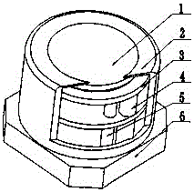
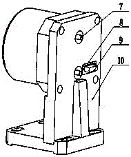
[0018] As shown in the figure, this solution includes a lens, a cooling cavity, a driver, a water pipe, a base, a water inlet, a water outlet and a support; the lens is bonded to the cooling cavity; one end of the driver is connected to the lens, and the other end is fixedly connected to the base; One end of the water pipe is connected to the cooling cavity, and the other end is fixedly connected to the base; the base is fixed on the support; ...


PUM


Abstract

The present invention provides a wave of correction devices, which include lens, cooling cavity, driver, water pipe, base, water inlet, outlet, and support;The other end is fixed with the base; one end of the water pipe is connected to the cooling cavity, and the other end is fixed with the base; the base is fixed on the support;The water pores on the seat correspond to one -to -one pores.This scheme can load different loads on the drive according to the application requirements. The mirror movement moves up and down under the action of the driver, so that the mirror surface deforms, thereby correcting the wave surface.The influence, avoid the introduction of unnecessary extra extension.

Description

technical field [0001] The invention relates to the field of wavefront correction in an adaptive optical system, in particular to a wavefront defocus correction device. Background technique [0002] In the optical system, there are various optical aberrations. For the unstable cavity thin-plate laser, the defocusing phenomenon of the wavefront is unavoidable. During the loading process of the laser, as the power increases, the defocus in the cavity will change, resulting in the deterioration of the beam quality of the output laser, and it is difficult to improve the energy concentration. In order to correct the defocusing in the cavity, the usual method is to place a defocusing mirror or lens in the optical path for passive compensation correction. Since the shape and size of the defocusing amount changes with the laser loading process, it is often not effective. To solve the defocusing in the cavity, there is always a defocusing aberration in the system, which is the defic...

Claims


Application Information

Patent Timeline
Patent Type & Authority Applications(China)
IPC IPC(8): G02B26/06
CPCG02B26/06
Inventor 李国会吴晶向汝建欧龙
Owner INST OF APPLIED ELECTRONICS CHINA ACAD OF ENG PHYSICS
Why Eureka
Try Eureka