A rotary billboard controlling device

A technology of control devices and billboards, applied in the direction of electrical program control, program control in sequence/logic controllers, etc., can solve problems such as visual fatigue, and achieve the effect of not being prone to visual fatigue

Inactive Publication Date: 2016-06-22
姚安宇
View PDF3 Cites 1 Cited by
  • Summary
  • Abstract
  • Description
  • Claims
  • Application Information

AI Technical Summary

Problems solved by technology

[0003] The purpose of the present invention is to provide a rotating billboard control device,

Method used


Image

  • A rotary billboard controlling device
  • A rotary billboard controlling device

Examples


Embodiment Construction

[0009] Below in conjunction with accompanying drawing and embodiment the present invention is described in further detail:

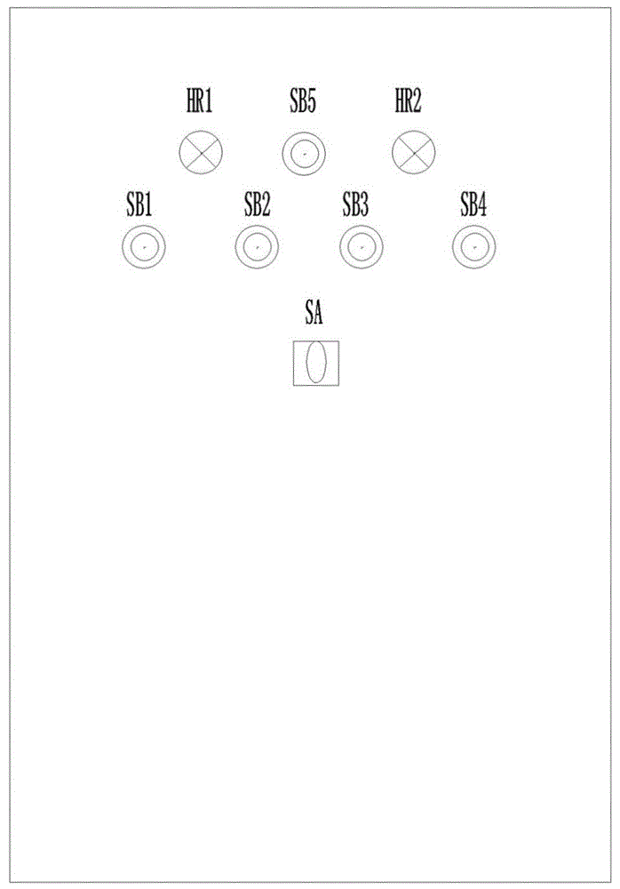
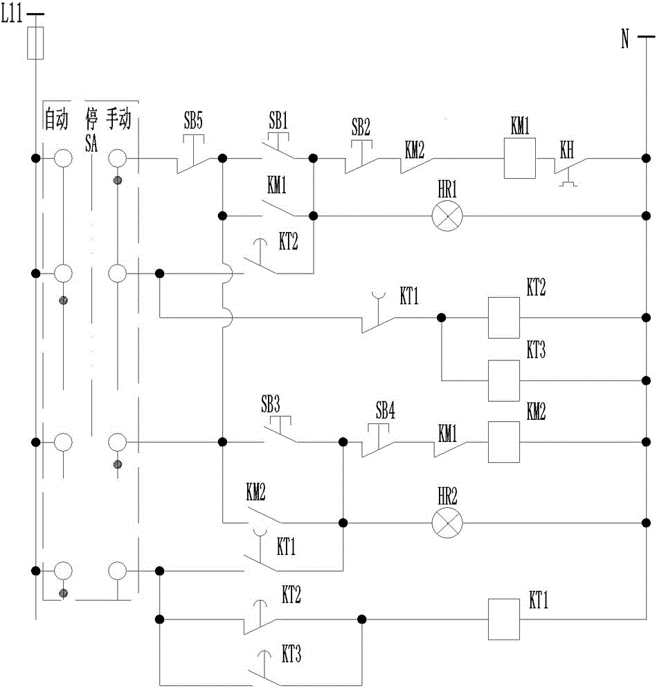
[0010] figure 1 and figure 2 The rotating billboard control device shown includes a control box body, a manual / auto switch SA, a total stop button SB5, a low-speed start button SB1, a low-speed stop button SB2, a high-speed start button SB3 and a high-speed switch are installed on the door of the box. Stop button SB4, low-speed contactor KM1, high-speed contactor KM2, low-speed thermal relay KH1, high-speed thermal relay KH2, first time relay KT1, second time relay KT2 and third time relay KT3 are installed in the box; manual / automatic switching Switch SA, total stop button SB5, low-speed start button SB1, low-speed stop button SB2, high-speed contactor KM2, low-speed contactor KM1 and low-speed thermal relay KH1 are connected in series to form a low-speed manual control circuit; low-speed contactor KM1 and low-speed start button SB1 are connected in p...


PUM


Abstract

The invention discloses a rotating billboard control device, which relates to the technical field of billboard control equipment manufacturing and comprises a low-speed manual control circuit, a high-speed manual control circuit, a low-speed automatic control circuit, a high-speed automatic control circuit and a conversion circuit. The invention can solve the problem that the existing rotating billboards easily cause visual fatigue to people.

Description

technical field [0001] The invention relates to the technical field of billboard control equipment manufacturing, in particular to a control device for rotating billboards. Background technique [0002] When people walk on the street, whether in a bustling metropolis or in a remote small town, they can see advertisements. When people turn on the TV and radio, they can often see and hear various advertisements; When you open newspapers and magazines, take a car, or go to the mall, you can feel that advertisements abound. Advertising has penetrated into all aspects of people's clothing, food, housing, and transportation. It is like an invisible bond that connects enterprises, businesses and consumers around the world. domain plays an important role. There are various forms of advertisements, and rotating advertisements are one of them. The existing rotating advertisements have only one rotation speed, which is easy to cause visual fatigue to the people watching it. Content...

Claims


Application Information

Patent Timeline
IPC IPC(8): G05B19/04
CPCG05B19/04
Inventor 姚安宇
Owner 姚安宇
Why Eureka
Try Eureka