

Track planning method for robot joint space conveyor belt following movement
A technology for robot joint and trajectory planning, applied in two-dimensional position/channel control and other directions, to achieve the effect of smooth joint velocity curve and simple visual algorithm
- Summary
- Abstract
- Description
- Claims
- Application Information
AI Technical Summary
Problems solved by technology
Method used
Image

Examples
Embodiment Construction
[0037] The present invention will be described in further detail below in conjunction with the embodiments and accompanying drawings.
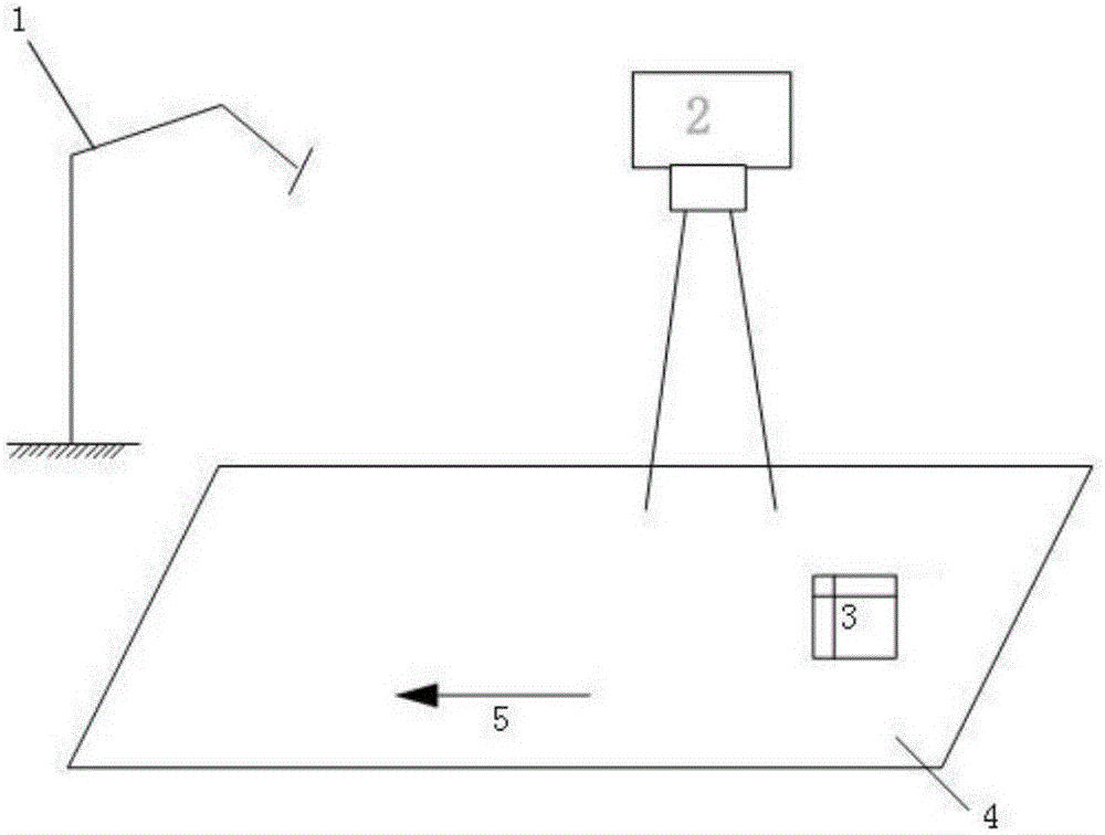
[0038] The present invention uses SCARA robot (attached Figure 4 Shown) is the experimental object, and its bar parameters are: L1=L2=300cm, L3=200cm, and the following algorithm proposed by the present invention is applied to it. The test environment is attached figure 1 As shown, the conveyor belt is installed on the X-axis of the Cartesian coordinate system and moves at a constant speed with a speed of 133.33mm / s.
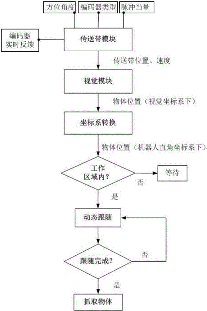
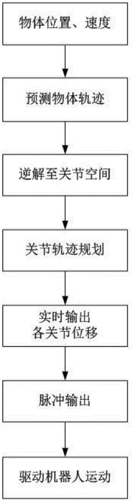
[0039] The entire follow-up process is attached figure 2 It is: when the vision module detects the target object, the program judges whether the following condition is satisfied, and if it is satisfied, it will follow dynamically. The so-called dynamic follow refers to reading the position of the target object every 4ms (the interpolation time of the control system) and predicting it. , the robot moves towards the predicted...
PUM
 Abstract
Description
Claims
Application Information