SCARA dynamic box pasting function implementation method

An implementation method, a technology for sticking boxes, applied in the directions of manipulators, program-controlled manipulators, manufacturing tools, etc., can solve the problems of poor box consistency, low efficiency, and increased labor costs.

Pending Publication Date: 2021-07-20
WUXI XINJIE ELECTRICAL
View PDF6 Cites 2 Cited by
  • Summary
  • Abstract
  • Description
  • Claims
  • Application Information

AI Technical Summary

Problems solved by technology
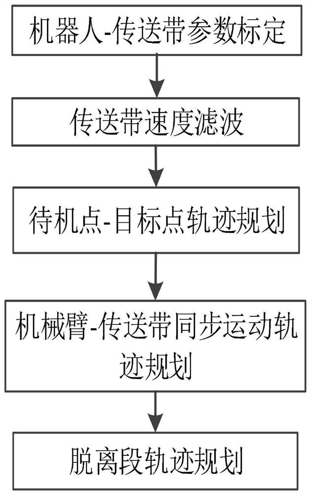
Manual box sticking increases labor costs, the efficiency is not high, and the consistency of the box is not good, so it is difficult for unskilled workers to stick it accurately
For visual static box pasting, the box pasting operation can only be completed after the conveyor belt is completely stopped. Such frequent start and stop increases the wear and tear of the motor and conveyor belt, and this solution needs to cooperate with the front-end paper feeding process and the back-end box forming process, and the system fails. high risk
[0003] After searching, the Chinese patent publication number is CN108674922A, which discloses the PID following algorithm. It is necessary to adjust the PID parameters according to the speed of the conveyor belt, otherwise the following accuracy is not ideal
[0004] The above patents also have the following disadvantages: the use of PID following algorithm limits the application scenarios, which greatly limits the upgrade and transformation of packaging manufacturers' box-attaching systems. Some dynamic box-attaching solutions use cameras to take pictures in real time, and the vision system calculates the points. Passing it to the robot, this method has relatively high requirements for the camera, the image acquisition environment is relatively harsh, and the image processing algorithm is also very complicated. This method is difficult to apply in engineering

Method used


Image

  • SCARA dynamic box pasting function implementation method
  • SCARA dynamic box pasting function implementation method
  • SCARA dynamic box pasting function implementation method

Examples


Embodiment Construction

[0034] The following will clearly and completely describe the technical solutions in the embodiments of the present invention with reference to the accompanying drawings in the embodiments of the present invention. Obviously, the described embodiments are only some, not all, embodiments of the present invention.

[0035] In describing the present invention, it should be understood that the terms "upper", "lower", "front", "rear", "left", "right", "top", "bottom", "inner", " The orientation or positional relationship indicated by "outside", etc. is based on the orientation or positional relationship shown in the drawings, and is only for the convenience of describing the present invention and simplifying the description, rather than indicating or implying that the referred device or element must have a specific orientation, so as to Specific orientation configurations and operations, therefore, are not to be construed as limitations on the invention.

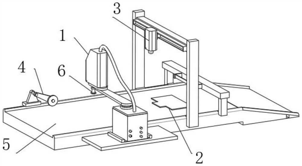
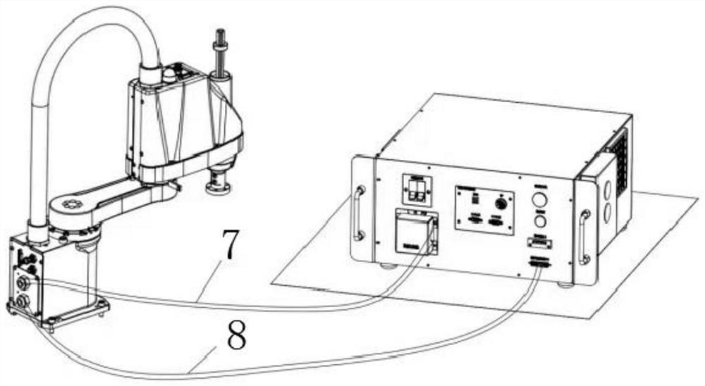
[0036] 2. Reference Fig...


PUM


Abstract

The invention belongs to the technical field of industrial robot control, and particularly relates to an SCARA dynamic box pasting function implementation method. The method comprises an SCARA robot dynamic box pasting scheme, a mechanical arm, a box, a camera module, an encoder, a conveying belt, a to-be-pasted gift box, a power cable and an encoder cable. An SCARA robot dynamic box pasting scheme comprises a robot-conveying belt position calibration module, a conveying belt speed filtering module, a standby point-target point trajectory planning module, a mechanical arm-conveying belt synchronous motion trajectory planning module and a module for establishing a disengaging trajectory planning and error compensation model after dynamic tracking is completed. The invention provides a position superposition scheme, the dynamic box pasting process is decomposed into synchronous movement in the direction of the conveying belt and point-to-point movement from a standby point to a box pasting point, and in order to enable the mechanical arm and the conveying belt to achieve ideal tracking precision in a following section, a synchronous movement position compensation model is established to compensate the position deviation of the following section.

Description

technical field [0001] The invention relates to the technical field of industrial robot control, in particular to a method for realizing the function of SCARA dynamic pasting boxes. Background technique [0002] With the improvement of national living standards, the demand for gift boxes, packaging boxes, etc. is also increasing. In actual use, it is necessary to stick the outer skin of the box and the inner lining of the cardboard together. At present, packaging companies mainly adopt manual box sticking and visual static box sticking schemes. Manual box sticking increases the labor cost, the efficiency is not high, and the consistency of the box is not good, so it is difficult for unskilled workers to stick it accurately. For visual static box pasting, the box pasting operation can only be completed after the conveyor belt is completely stopped. Such frequent start and stop increases the wear and tear of the motor and conveyor belt, and this solution needs to cooperate wi...

Claims


Application Information

Patent Timeline
Patent Type & Authority Applications(China)
IPC IPC(8): B25J9/16
CPCB25J9/1664B25J9/1697
Inventor 胡忠全蒋勇张迪葛杨李新
Owner WUXI XINJIE ELECTRICAL
Why Eureka
Try Eureka