Subject tracking apparatus, subject region extraction apparatus, and control methods therefor

a tracking apparatus and subject technology, applied in the field of subject tracking apparatus, subject region extraction apparatus, and control methods therefor, can solve the problems of subject tracking accuracy degrading, subject cannot be precisely tracked in subsequent frames, etc., and achieve the effect of improving subject tracking accuracy

Active Publication Date: 2011-06-23
CANON KK
View PDF8 Cites 54 Cited by
  • Summary
  • Abstract
  • Description
  • Claims
  • Application Information

AI Technical Summary

Benefits of technology

[0013]The present invention provides a subject tracking apparatus and a control method therefor, which perform subject tracking based on the degree of correlation between a reference image and an input image and in which the subject tracking accuracy is improved even when the visual aspect of a subject changes.
[0020]With this configuration, according to an aspect of the present invention, the subject tracking accuracy is improved even when the visual aspect of a subject changes in a subject tracking apparatus and a control method therefor, which perform subject tracking based on the degree of correlation between a reference image and an input image.

Problems solved by technology

However, if, for example, the subject is the face of a person and the face orientation may change or the face may be shielded by a physical object, the tracking accuracy may degrade due to the use of the same reference image.
However, in this method, if the subject is temporarily hidden behind a physical object, a region different from the subject is used as the reference image in the next tracking process, so the subject cannot be precisely tracked in subsequent frames.
When the subject is tracked using such a reference image which includes unwanted images in large amounts, the subject tracking accuracy may degrade as a region different from the target region may be tracked due to the influence of factors associated with the unwanted images.

Method used


Image

  • Subject tracking apparatus, subject region extraction apparatus, and control methods therefor
  • Subject tracking apparatus, subject region extraction apparatus, and control methods therefor
  • Subject tracking apparatus, subject region extraction apparatus, and control methods therefor

Examples


first embodiment

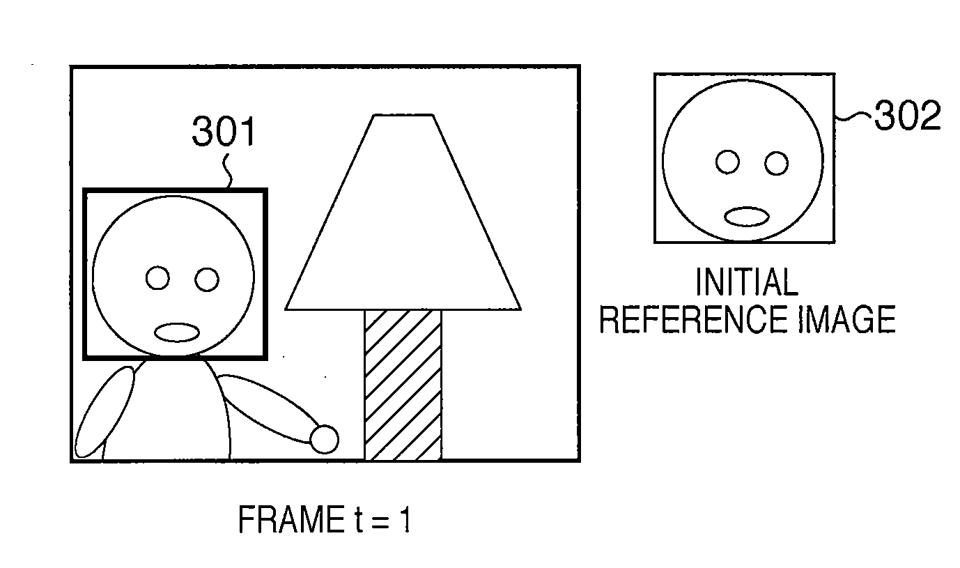
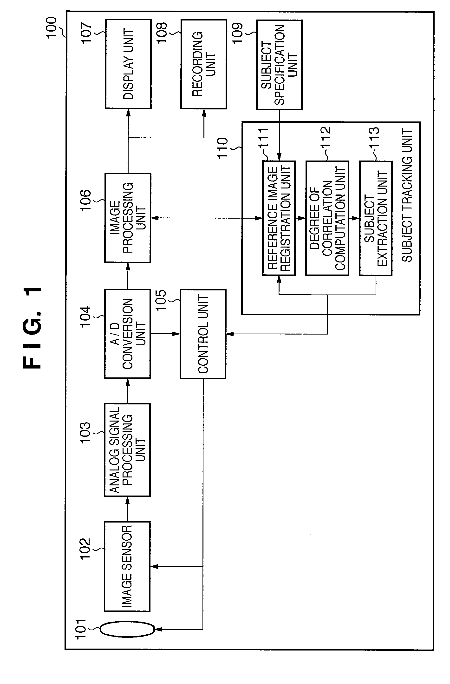
[0036]FIG. 1 is a block diagram showing an example of the functional configuration of an image capturing apparatus 100 as an example of a subject tracking apparatus according to the first embodiment of the present invention. A lens unit 101 is an imaging optical system, and generally includes a plurality of lenses including a focus adjustment lens. The lens unit 101 forms an optical image of a subject on the image sensing surface of an image sensor 102. The image sensor 102 is a photoelectric conversion element such as a CCD image sensor or a CMOS image sensor, and converts the optical image of the subject into an electrical signal for each pixel. This electrical signal is an analog video signal indicating the subject image captured by the image sensor 102. The image sensor 102 can output video signals in time series at a predetermined frame rate by continuously repeating image capture and output. An “image” in the following description is synonymous with a video signal of one frame...

second embodiment

[0071]An image capturing apparatus as an example of a subject tracking apparatus according to the second embodiment of the present invention will be described next with reference to FIGS. 4 to 6C by focusing attention mainly on differences from the first embodiment. Note that the same reference numerals as in FIGS. 1 to 3D according to the first embodiment denote the same configurations and operations in FIGS. 4 to 6C, and a repetitive description thereof will not be given.

[0072]An image capturing apparatus 400 according to this embodiment is different from the image capturing apparatus 100 in the first embodiment in that a subject tracking unit 401 has a configuration different from the subject tracking unit 110. More specifically, the image capturing apparatus 400 is different from the image capturing apparatus 100 in the first embodiment in that in the former a feature amount extraction unit 402, a feature matching degree determination unit 403, and a determination threshold sett...

third embodiment

Configuration and Operation of Image Capturing Apparatus

[0087]FIG. 7 is a block diagram showing an example of the functional configuration of an image capturing apparatus 700 as an example of a subject tracking apparatus according to the third embodiment of the present invention. The same reference numerals as in FIG. 1 denote the same functional blocks in FIG. 7, and a repetitive description thereof will not be given.

[0088]A subject region extraction unit 710 extracts a target subject region from a region specified by a subject specification unit 109 in the image supplied from an image processing unit 106. The subject region extraction unit 710 includes a feature amount extraction unit 711, misalignment detection unit 712, and region correction unit 713 (all will be described later).

[0089]The feature amount extraction unit 711 extracts feature amounts indicating the feature of the target subject from a predetermined region in the region specified by the subject specification unit 1...


PUM


Abstract

A subject tracking apparatus which performs subject tracking based on the degree of correlation between a reference image and an input image is disclosed. The degree of correlation between each of a plurality of reference images based on images input at different times, and the input image is obtained. If the maximum degree of correlation between a reference image based on a first input image among the plurality of reference images and the input image is equal to or higher than a threshold, a region with a maximum degree of correlation with a first reference image is determined as a subject region. Otherwise, a region with a maximum degree of correlation with a reference image based on an image input later than the first input image is determined as a subject region.

Description

BACKGROUND OF THE INVENTION[0001]1. Field of the Invention[0002]The present invention relates to a subject tracking apparatus, a subject region extraction apparatus, and control methods therefor.[0003]2. Description of the Related Art[0004]An image processing technique of detecting a specific subject in one frame of images that are sequentially supplied in time series, and tracking the detected subject in subsequent frames, is very useful. A technique of detecting and tracking a human body region (for example, a face region) in a moving image, for example, can be employed in a wide variety of fields such as a conference call, a man-machine interface, security, a monitor system for tracking a specific subject, and image compression. Some digital cameras and digital video cameras which incorporate this image processing technique are known to execute exposure control and focus control so as to appropriately capture a subject specified in the image displayed on an electronic viewfinder....

Claims


Application Information

Patent Timeline
Patent Type & Authority Applications(United States)
IPC IPC(8): G06K9/00G06K9/46
CPCG06T7/204G06T2207/10016G06T2207/30201G06T2207/20104G06T2207/10024G06T7/248
Inventor TSUJI, RYOSUKE
Owner CANON KK
Why Eureka
Try Eureka