Coating machine

A technology of coating machine and rack, applied in the direction of coating, device for coating liquid on the surface, etc., can solve the problems of large occupied space, poor equipment stability, low work efficiency, etc.

Active Publication Date: 2016-06-29
CHANGZHOU JUNHE TECH
View PDF12 Cites 21 Cited by
  • Summary
  • Abstract
  • Description
  • Claims
  • Application Information

AI Technical Summary

Problems solved by technology

[0003] 1. Most of the existing coating equipment is single-station coating. During the coating process, the workpiece needs to be loaded into the workpiece basket, and then placed in the coating equipment for soaking and drying. This can only achieve single-station coating. For the work of the station, after the coating is completed, it is necessary to stop the machine and take out the workpiece basket from the coating equipment, so as to pour out the workpieces in the workpiece basket, and then put the next batch of workpieces to be coated into the workpiece basket , placed in the coating equipment again for coating, such work efficiency is low and cannot meet the requirements of mass production
[0004] 2. During the coating process, the workpiece needs to be put into the workpiece basket, soaked by putting the workpiece basket into the coating liquid tank, and after the soaking is completed, dry the excess coating liquid on the surface of the workpiece; the existing workpiece basket The floating or plane plus pin connection method is often used, so that the container causes poor stability of the equipment, low work efficiency, and also increases the workload of the staff; in addition, there are also clamping devices to assemble the workpiece basket However, due to structural design defects, the existing clamping device occupies a large space and cannot completely guarantee the simultaneous clamping and loosening of the workpiece basket, which affects work efficiency and use effect
[0005] 3. During the coating process, the workpiece needs to be soaked in the coating solution. The existing coating solution is filled in a cylinder with an upper end opening. When the workpiece is soaked, the workpiece basket containing the workpiece is moved by driving or electric hoist Put it in the cylinder, soak the workpiece with the coating liquid in the cylinder, and then lift it to the designated place. After the workpiece basket is lifted out of the cylinder, there will be excess coating liquid on the surface of the workpiece, which will Dripping during the lifting process pollutes the environment and wastes the coating liquid. In this way, the cylinder is only used for filling the coating liquid, and the position cannot be changed according to the needs, which is difficult to meet Coating work requirements for automatic coating machines
[0006] 4. During the coating process, the workpiece needs to be loaded into the workpiece basket or poured out of the workpiece basket, and then transported to the coating machine for surface coating. The current way of loading or pouring the workpiece into the workpiece basket , Most of them are operated by traditional manual methods, which reduces the work efficiency and the work intensity of the staff is also high. In addition, some of them are realized by simple mechanical methods to reduce the labor intensity of the staff and the corresponding Improve work efficiency, but some current structures still cannot meet the requirements of automatic coating due to unreasonable structural design
[0007] To sum up, the coating machine with the existing structure has low degree of automation and low work efficiency, and cannot meet the requirements of automatic production

Method used


Image

  • Coating machine
  • Coating machine
  • Coating machine

Examples


Embodiment Construction

[0058] In order to make the objectives, technical solutions, and advantages of the embodiments of the present invention clearer, the technical solutions of the embodiments of the present invention will be described clearly and completely in conjunction with the accompanying drawings of the embodiments of the present invention. Obviously, the described embodiments are part of the embodiments of the present invention, rather than all of the embodiments. Based on the described embodiments of the present invention, all other embodiments obtained by a person of ordinary skill in the art without creative work shall fall within the protection scope of the present invention.

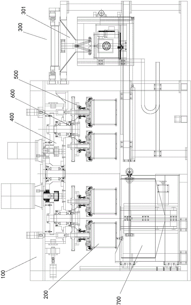
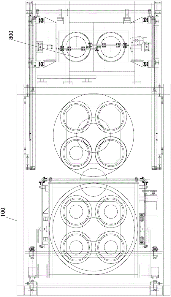
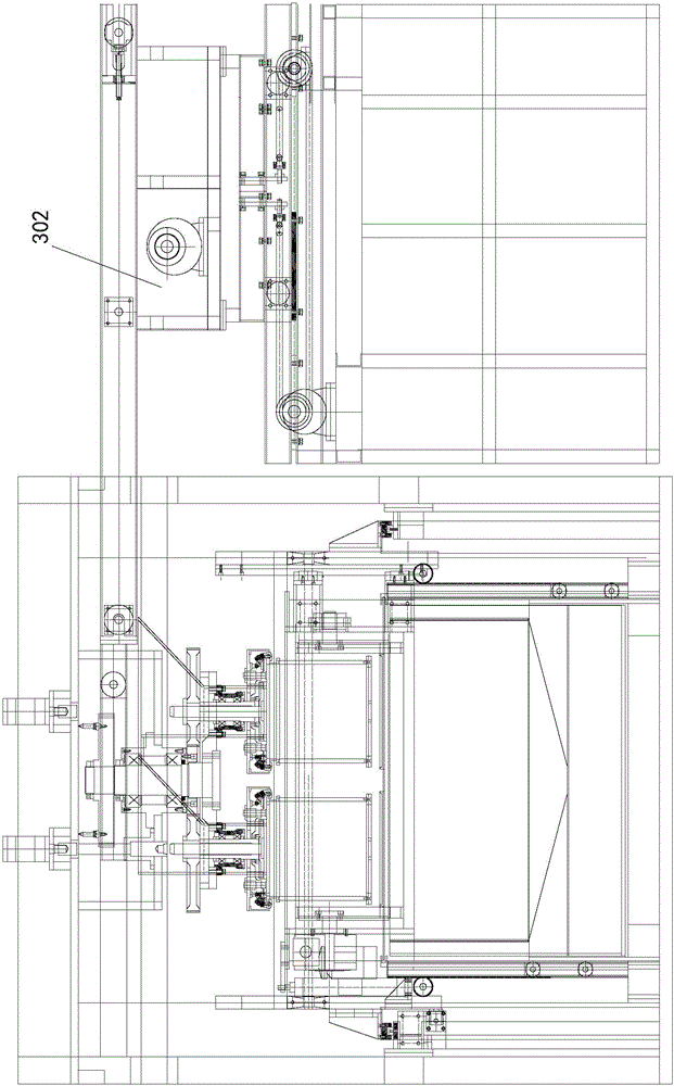
[0059] See figure 1 , 2 3. The coating machine includes a machine frame 100, a workpiece basket 200, and a feeding mechanism 300 for adding workpieces to the workpiece basket. The machine frame is provided with a station rotation device 400 for changing the working position of the workpiece basket. At least two set...


PUM


Abstract

The invention discloses a coating machine which comprises a rack and a workpiece basket. The coating machine further comprises a feeding mechanism for adding workpieces into the workpiece basket. A working station rotating device for changing the work position of the workpiece basket is arranged on the rack and at least provided with two sets of clamping and rotating devices for clamping or loosening the workpiece basket and driving the workpiece basket to rotate, and centrifugal driving mechanisms arranged on the working station rotating device and used for driving the clamping and rotating devices to rotate. A dipping machine and a dipping machine lifting device for driving the dipping machine to enable the workpiece basket to be soaked therein, and a walking turnover device are arranged below the clamping and rotating devices, and the walking turnover device is used for conveying the fed workpiece basket to the positions of the clamping and rotating devices to be clamped by the clamping and rotating devices. The coating machine automatically conveys the workpieces needing to be coated into coating equipment, the coated workpieces are automatically discharged, the automation degree is high, and the coating efficiency is improved.

Description

Technical field [0001] The invention relates to a coating machine. Background technique [0002] The surface coating machine technology of the coating machine is the technology of coating a new material on the surface of the product; the surface coating is the technology of forming a film on the surface of the substrate to improve the protection of the surface. After the new material is sprayed on the surface of the product, it can meet the requirements of the surface performance, the bonding strength of the coating layer and the matrix material to meet the requirements of the working conditions, good economy, and good environmental protection. However, the existing coating machine has the following defects: [0003] 1. Most of the existing coating equipment is single-station coating. During the coating process, the workpiece needs to be put into the workpiece basket, and then placed in the coating equipment for soaking and spin-drying. This can only achieve single-station coating...

Claims


Application Information

Patent Timeline
Patent Type & Authority Applications(China)
IPC IPC(8): B05C3/02B05C13/00B05C9/12
CPCB05C3/02B05C9/12B05C13/00
Inventor 钱永键吴伟峰吴昊
Owner CHANGZHOU JUNHE TECH
Why Eureka
Try Eureka