Pulse welding equipment and control method thereof

A technology of pulse welding and control method, applied in welding equipment, arc welding equipment, metal processing equipment, etc., to achieve the effect of eliminating wire feeding overshoot

Active Publication Date: 2016-06-29
PANASONIC WELDING SYST TANGSHAN
View PDF4 Cites 5 Cited by
  • Summary
  • Abstract
  • Description
  • Claims
  • Application Information

AI Technical Summary

Problems solved by technology

[0009] The present invention aims to provide a pulse welding equipment and its control method aiming at the wire feeding overshoot problem existing in the existing pulse welding equipment

Method used


Image

  • Pulse welding equipment and control method thereof
  • Pulse welding equipment and control method thereof
  • Pulse welding equipment and control method thereof

Examples


no. 1 example

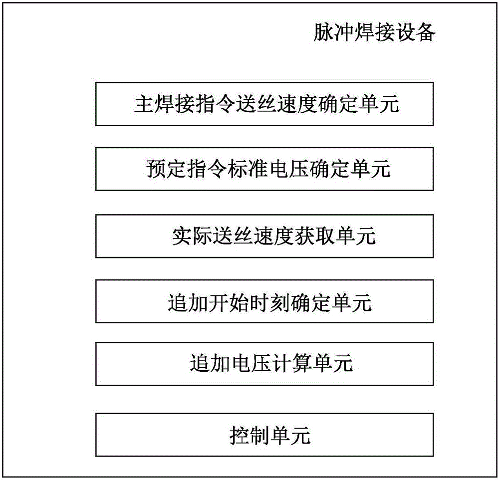
[0029] Refer below Figure 1 to Figure 3 A first embodiment of the present invention is described. figure 1 The software structure of the pulse welding apparatus of the first embodiment is shown.

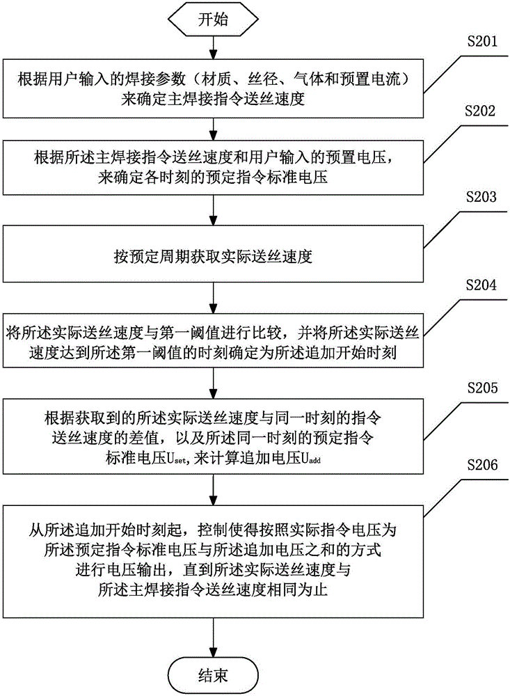
[0030] Such as figure 1 As shown, the pulse welding equipment of the present invention includes: a main welding command wire feeding speed determination unit, which is used to determine the main welding command wire feeding speed according to the welding parameters (including material, wire diameter, gas and preset current) input by the user; The predetermined command standard voltage determination unit is used to determine the predetermined command standard voltage at each time according to the main welding command wire feeding speed and the preset voltage input by the user; the actual wire feeding speed acquisition unit is used to obtain the actual wire feeding speed according to a predetermined period wire feeding speed: an additional start time determining unit, configured t...

no. 2 example

[0045] Refer below Figure 4 and 5 A second embodiment of the present invention is described. Since the software configuration and control method of the second embodiment are basically the same as those of the first embodiment, the description will not be repeated here. Only the differences between the two are described below.

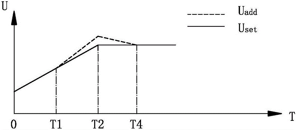
[0046] The second embodiment differs from the first embodiment in the control unit (ie, control step S406). In the second embodiment, step S406 is based on the step S206 of the first embodiment, and the following steps are added: at the time T2 (also called "holding time") from the command wire feed speed to the main welding command wire feed speed ), the CPU controls the voltage output in such a manner that the actual command voltage at the holding time is held for a predetermined period (the period of T2-T3).

[0047] After the predetermined period (the period of T2-T3) ends, the CPU controls to continue to carry out the voltage output according ...


PUM


Abstract

The invention provides pulse welding equipment and a control method thereof. The pulse welding equipment comprises a main welding instruction wire-feeding speed determining unit, a preset instruction standard voltage determining unit, an actual wire-feeding speed acquiring unit, a supplement beginning time determining unit, a supplement voltage calculating unit and a control unit. According to the pulse welding equipment and the control method thereof, the wire-feeding overshoot can be automatically calculated, the voltage can be increased according to the wire-feeding overshoot, and therefore wire-feeding overshooting can be effectively eliminated.

Description

[technical field] [0001] The invention relates to the field of welding, in particular to a welding device and a control method for welding by means of pulse welding. [Background technique] [0002] Welding equipment (also known as welding machines) has been widely used in various manufacturing industries. According to different welding methods, welding equipment can be divided into short-circuit transition and pulse welding. Pulse welding has the advantages of arc compression effect, arc concentration, and good stiffness, so it is widely used in thin plate welding (such as welding of non-ferrous metals such as stainless steel, steel, and titanium). Hereinafter, welding equipment that welds in a pulsed manner is referred to as pulse welding equipment. [0003] Normally, when the torch switch is turned on, the wire feed motor starts and starts feeding the wire. The wire-feeding motor makes the wire-feeding speed rise to the target value of the wire-feeding speed of the main...

Claims


Application Information

Patent Timeline
Patent Type & Authority Applications(China)
IPC IPC(8): B23K9/09B23K9/12
CPCB23K9/09B23K9/124
Inventor 苏立虎安小东孙永涛谷孝满
Owner PANASONIC WELDING SYST TANGSHAN
Why Eureka
Try Eureka