Supercharge Your Innovation With Domain-Expert AI Agents!

Robot spraying device

A spraying device and robot technology, applied in spraying devices, manipulators, manufacturing tools, etc., can solve problems such as potential safety hazards, low efficiency, and inability to spray cylindrical molds

Active Publication Date: 2016-06-29
上海普莱克斯自动设备制造有限公司
View PDF8 Cites 2 Cited by
  • Summary
  • Abstract
  • Description
  • Claims
  • Application Information

AI Technical Summary

Problems solved by technology

[0002] The existing robot spraying device uses the robot to spray the plane of the mold. As we all know, the robot spraying has great defects when spraying the cylindrical mold. It can only spray the bottom surface of the cylindrical mold and the semicircle close to the robot within the robot’s range of motion. , due to the movement limitation of the robot, the other semicircle of the cylindrical mold cannot be sprayed
When manual spraying is used, not only the labor force is large, the efficiency is low, but also there are potential safety hazards.
[0003] From the above text, it is not difficult to see that the previous robot spraying system has great deficiencies and defects

Method used


Image

  • Robot spraying device
  • Robot spraying device

Examples


Embodiment Construction

[0020] The present invention will be further described below with reference to the accompanying drawings.

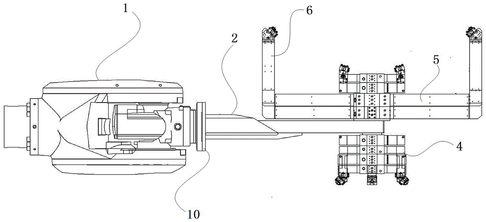
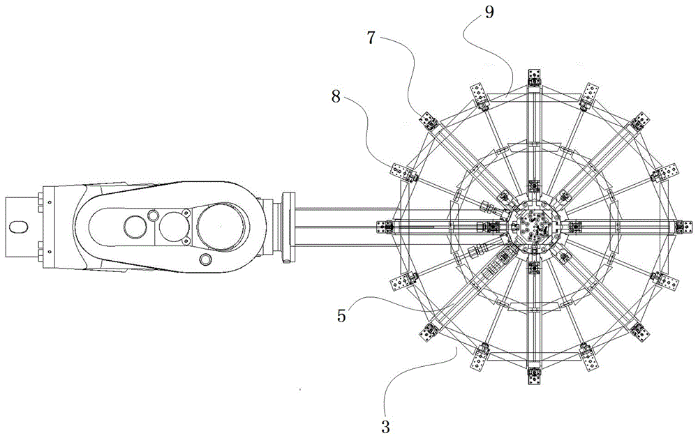
[0021] The invention discloses a robot spraying device, which is different from the prior art in that it includes a robot arm 1, which is connected to a circular bearing bracket 3 through a connecting rod 2, and the robot arm 1 and the connecting rod 2 are connected by a The flange 10 is connected, and a fixed block 4 is provided below the joint between the connecting rod 2 and the circular bearing bracket 3. There are several horizontal brackets 5 distributed from the center of the circle to the surroundings in the said circular bearing bracket 3. One end of the horizontal bracket 5 It is fixed at the center of circle of the circular support bracket 3, the other end of the horizontal bracket 5 is suspended, the suspended end of the horizontal bracket 5 is provided with a vertical bracket 6 vertically perpendicular to the horizontal bracket 5, and the lower end of the ver...


PUM


Abstract

The invention discloses a robot spraying device. A robot arm is connected with a circular bearing bracket through a connecting rod; multiple layers of fixed blocks are arranged below the connecting place between the connecting rod and the circular bearing bracket; multiple horizontal brackets are dispersed on the circular bearing bracket from circle center to periphery; one ends of the horizontal brackets are fixed in the circle center of the circular bearing bracket, and the other ends of the horizontal brackets are suspended; vertical brackets longitudinally perpendicular to the horizontal brackets are arranged at the suspended ends of the horizontal brackets; the lower ends of the vertical brackets are fixedly connected with the suspended ends of the horizontal brackets; and parting agent atomizers or cooling air blowing atomizers are alternately arranged at the upper ends of the vertical brackets in sequence. The robot spraying device has the advantages of realization of full-automatic efficient spraying, capability of realizing 360-degree high-speed spraying, effective improvement of the production efficiency and more stable spraying quality.

Description

technical field [0001] The invention relates to the technical field of forging machine peripheral equipment, in particular to a robot spraying device, and particularly to its mechanical connection structure. Background technique [0002] The existing robot spraying device uses the robot to spray the plane of the mold. As we all know, the robot spraying has great defects when spraying the cylindrical mold. It can only spray the bottom surface of the cylindrical mold and the semicircle close to the robot within the robot’s range of motion. , due to the movement limitation of the robot, the other semicircle of the cylindrical mold cannot be sprayed. When artificial spraying is adopted, not only the labor force is large, the efficiency is low, but also there are potential safety hazards. [0003] From the above text, it is not difficult to see that the previous robot spraying system has great deficiencies and defects. Therefore, it is necessary to make further improvements to ...

Claims


Application Information

Patent Timeline
IPC IPC(8): B25J11/00B05B13/04
CPCB05B13/0431B25J11/0075
Inventor 高桥昌志
Owner 上海普莱克斯自动设备制造有限公司
Features
  • R&D
  • Intellectual Property
  • Life Sciences
  • Materials
  • Tech Scout
  • Unparalleled Data Quality
  • Higher Quality Content
  • 60% Fewer Hallucinations
Learn More