Lift car energy-saving device

An energy-saving equipment and car technology, applied in lifts, elevators in buildings, transportation and packaging, etc., can solve problems such as energy waste, poor air quality, and poor air replacement effects, and achieve convenient use and power saving , the effect of saving energy loss

Inactive Publication Date: 2016-06-29
ANHUI REGON ELEVATOR SERVICES CO LTD
View PDF8 Cites 2 Cited by
  • Summary
  • Abstract
  • Description
  • Claims
  • Application Information

AI Technical Summary

Problems solved by technology

For elevators that lift vertically, due to the relatively closed space inside the car, the air quality in the car is poor. In some elevators, fans are used to guide the air in the car to circulate between the air in the elevator shaft to achieve air replacement. The long-term operation of the fan leads to energy waste. If the diversion speed of the fan to the air is too fast, it will easily cause discomfort to the people in the car, and if the diversion speed is too slow, the air replacement effect will not be good.

Method used


Image

  • Lift car energy-saving device
  • Lift car energy-saving device

Examples


Embodiment Construction

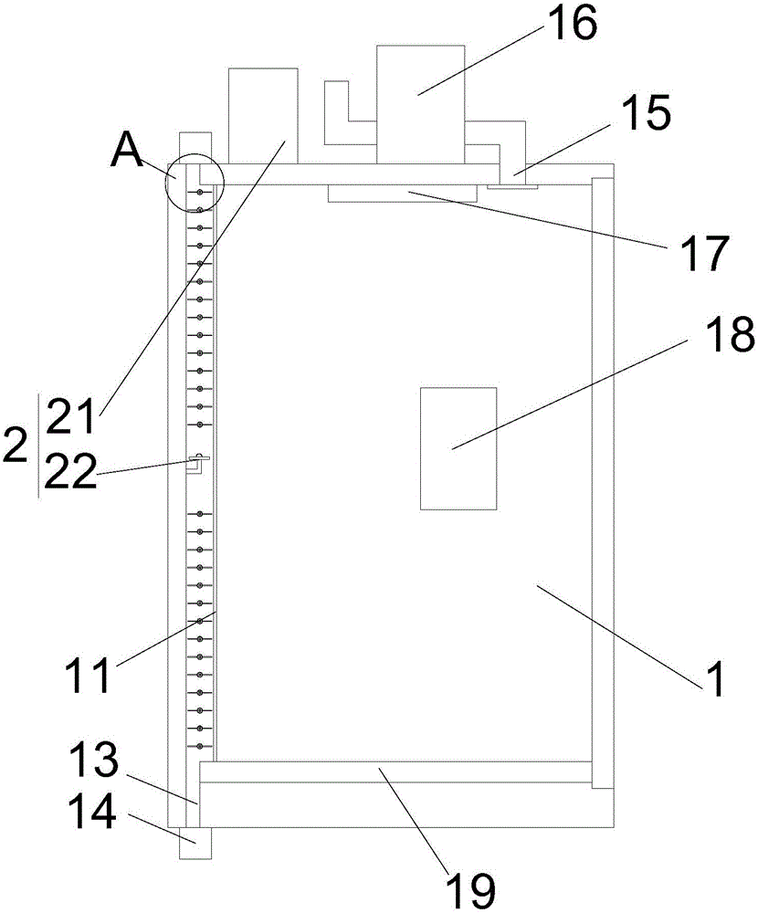
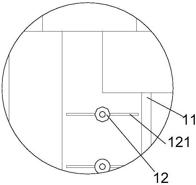
[0017] refer to figure 1 with figure 2 As shown, a car energy-saving device proposed by the present invention includes a car 1 and a control mechanism 2;

[0018] A net plate 11 is installed in the car 1, and the net plate 11 is parallel to the car wall on the side of the car door of the car 1, and a plurality of Rotating shaft 12, the rotating shaft 12 is parallel to the length direction of the screen plate 11 and distributed along the height direction of the screen plate 11, the two ends of the rotating shaft 12 are respectively rotatably installed on the two adjacent car walls of the car door of the car 1; The car floor of car 1 and the car top of car 1 are provided with ventilation holes 13, and the ventilation holes 13 are located on the side of the rotating shaft 12 away from the screen plate 11. An air filter device 14 is installed on the car 1 corresponding to the position of the ventilation holes 13. Windshields 121 are installed on the opposite sides on the shaft ...


PUM


Abstract

The invention provides a lift car energy-saving device which comprises a lift car and a control mechanism. A mesh plate is installed in the lift car and is parallel to the car wall on the side, opposite to a car door, of the lift car. Multiple rotary shafts are installed between the mesh plate and the car wall on the side, opposite to the car door, of the lift car. The rotary shafts are parallel to the length direction of the mesh plate and are distributed in the height direction of the mesh plate. The two ends of each rotary shaft are rotationally installed on two adjacent car walls of the car door of the lift car. Ventilation holes are formed in a car bottom and a car top of the lift car and located in the sides, away from the mesh plate, of the rotary shafts. Air filter devices are installed at the positions, corresponding to the ventilation holes, on the lift car. Air baffles are arranged on the two opposite sides of each rotary shaft. An air guide hole is further formed in the car top of the lift car. A draught fan is installed on the lift car. A draught fan air inlet communicates with the air guide hole. A lighting lamp is installed in the lift car. The control mechanism comprises a control device, a pressure induction device and an air speed sensor. By the adoption of the lift car energy-saving device, the quality of air in the lift car can be effectively improved, and energy losses can be effectively reduced.

Description

technical field [0001] The invention relates to the technical field of elevator safety, in particular to a car energy-saving device. Background technique [0002] Elevator is a kind of vertical elevator powered by electric motor, equipped with box-shaped gondola, which is used for multi-storey buildings to take people or carry goods. There is also a step type, and the tread plate is installed on the crawler belt to run continuously, commonly known as an escalator or a moving walk. Fixed lifting equipment serving specified floors. A vertical elevator has a car running between at least two vertical or inclination angles of less than 15° rigid guide rails. The size and structure of the car are convenient for passengers to enter and exit or to load and unload goods. It is customary to use elevator as a general term for vertical transportation in buildings regardless of its driving mode. For elevators that lift vertically, due to the relatively closed space inside the car, th...

Claims


Application Information

Patent Timeline
Patent Type & Authority Applications(China)
IPC IPC(8): B66B11/02B66B5/00
CPCB66B11/024B66B5/0018
Inventor 周翔
Owner ANHUI REGON ELEVATOR SERVICES CO LTD
Why Eureka
Try Eureka