Unmanned aerial vehicle 360-degree electronic scanning obstacle avoidance radar

An electromagnetic and electromagnetic wave technology, applied in the field of UAV 360-degree electronic scanning obstacle avoidance radar

Inactive Publication Date: 2016-06-29
北京木牛领航科技有限公司
View PDF10 Cites 36 Cited by
  • Summary
  • Abstract
  • Description
  • Claims
  • Application Information

AI Technical Summary

Problems solved by technology

Accordingly, the claimed invention should not be construed as limited to solving any specific problems or deficiencies discussed herein.

Method used


Image

  • Unmanned aerial vehicle 360-degree electronic scanning obstacle avoidance radar
  • Unmanned aerial vehicle 360-degree electronic scanning obstacle avoidance radar
  • Unmanned aerial vehicle 360-degree electronic scanning obstacle avoidance radar

Examples


Embodiment Construction

[0100] The present invention will be described in detail below with reference to the drawings and examples. It should be noted that the listed embodiments and features thereof can be combined with each other in the absence of conflict.

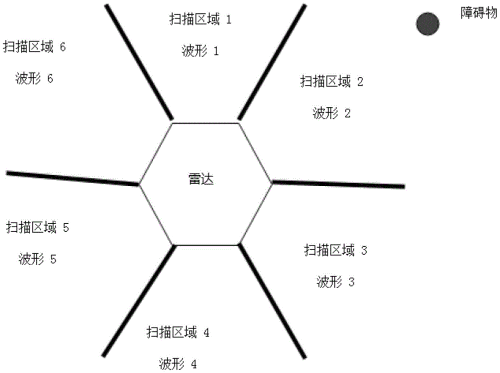
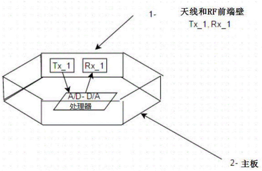
[0101] In the first embodiment, the top view profile structure of the proposed radar is in figure 1 shown in . A pair of transmitting and receiving antennas are placed on each side of the hexagonal structure. The entire 360 ​​degree circumference around the UAV or other vehicle on which the radar system is placed is divided into 6 scanned areas, e.g. figure 1Scan area 1 to scan area 6 in. Each scan area uses a specific waveform, for example, scan area 1 uses waveform 1, scan area 2 uses waveform 2, and so on. Every waveform must be different from every other waveform, or the waveforms will interfere with each other. This makes it possible to scan from obstacles within a scan area ( figure 1 Obstacles in middle scan area 2) will not cause...


PUM


Abstract

The invention provides a method for detecting objects, which includes the steps of: arranging non-rotating transmitting antennas and a receiving antenna in a position; emitting electromagnetic waveforms which are reflected by objects to be detected by each of the two or more non-rotating antennas, each of the waveforms being selected to be other waveforms which avoid to interfere emitted signals and received signals; receiving reflected electromagnetic echo signals reflected by the objects to be detected through the receiving antenna, and generating receiving signals corresponding to the electromagnetic echo signals; and treating the receiving signals so as to determine relative position information of the objects to be detected.

Description

technical field [0001] The invention relates to the field of radar-based detection, in particular to a 360-degree electronic scanning obstacle avoidance radar for unmanned aerial vehicles. Background technique [0002] Radar is an object detection system that uses radio waves to determine the range, altitude, direction, or speed of an object. It can be used to detect aircraft, ships, spacecraft, missiles, motor vehicles, weather formations, and terrain. Radar antennas emit pulses of radio waves or microwaves that bounce off any objects in their path. The object reflects a small portion of the wave's energy to the antenna, which is usually located at the same location as the transmitter. [0003] Modern uses of radar are highly diverse and include air and land traffic control, radar astronomy, air defense systems, anti-missile systems; marine radar to locate landmarks and other ships; aircraft collision avoidance systems; marine surveillance systems, space surveillance and ...

Claims


Application Information

Patent Timeline
Patent Type & Authority Applications(China)
IPC IPC(8): G01S13/42G01S13/93G01S13/933
CPCG01S13/42G01S13/93G01S13/343G01S13/933
Inventor 王宗博
Owner 北京木牛领航科技有限公司
Why Eureka
Try Eureka