

Optical fiber adapter
A fiber optic adapter and housing technology, applied in the field of optical communication, can solve the problems of long installation time and complicated operation, and achieve the effects of improving convenience, simple installation and removal process, and improved efficiency
- Summary
- Abstract
- Description
- Claims
- Application Information
AI Technical Summary
Problems solved by technology
Method used
Image

Examples
Embodiment 1
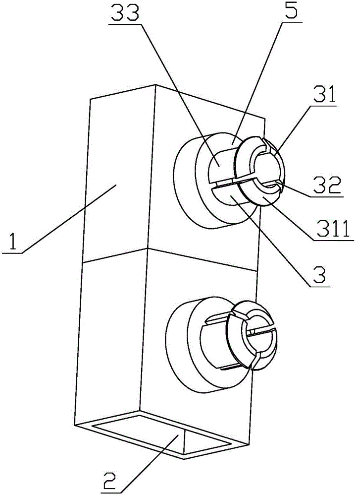
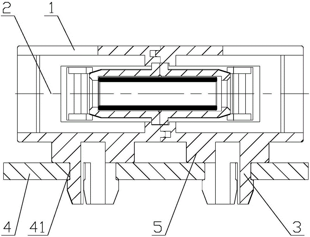
[0025] Such as figure 1 , figure 2 As shown, the fiber optic adapter of this embodiment includes a housing 1, and the housing 1 is provided with a cavity 2 for inserting an optical fiber. The fiber optic adapter also includes an elastic arm for inserting the housing 1 on the PCB board 4. 3. The elastic arm 3 is integrally arranged on the outer wall of the housing 1, the elastic arm 3 is provided with a hook 31, the axis of the elastic arm 3 is perpendicular to the axis of the housing 1, and the PCB board 4 is provided with a clamping joint hole 41 , the elastic arm 3 passes through the engaging hole 41 , and the hook portion 31 is engaged on the PCB 4 . In this embodiment, two elastic arms 3 are arranged on the outer wall of the housing 1 , and the connecting line of the two elastic arms 3 is parallel to the axis of the housing 1 .
[0026] In this embodiment, the elastic arm 3 is cylindrical, and the elastic arm 3 is provided with several openings 32, the openings 32 are e...
Embodiment 2
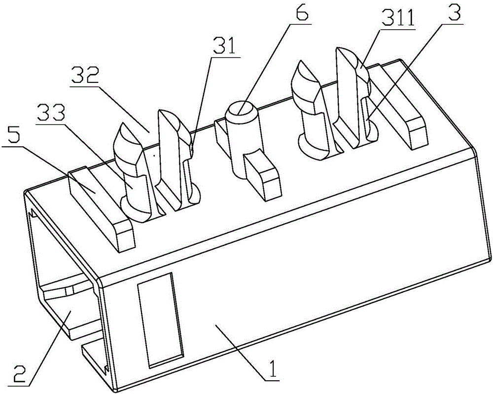
[0032] Such as image 3 , Figure 4 As shown, the fiber optic adapter of this embodiment includes a housing 1, and the housing 1 is provided with a cavity 2 for inserting an optical fiber. The fiber optic adapter also includes an elastic arm for inserting the housing 1 on the PCB board 4. 3. The elastic arm 3 is integrally arranged on the outer wall of the housing 1, the elastic arm 3 is provided with a hook 31, the axis of the elastic arm 3 is perpendicular to the axis of the housing 1, and the PCB board 4 is provided with a clamping joint hole 41 , the elastic arm 3 passes through the engaging hole 41 , and the hook portion 31 is engaged on the PCB 4 . In this embodiment, two elastic arms 3 are arranged on the outer wall of the housing 1 , and the connecting line of the two elastic arms 3 is parallel to the axis of the housing 1 .
[0033] In this embodiment, the hook portion 31 is provided with a chamfer 311 which is convenient for fitting the elastic arm into the locking...
Embodiment 3
[0040] Such as Figure 5 , 6 As shown, the fiber optic adapter of this embodiment includes a housing 1, and the housing 1 is provided with a cavity 2 for inserting an optical fiber. The fiber optic adapter also includes an elastic arm for inserting the housing 1 on the PCB board 4. 3. The elastic arm 3 is integrally arranged on the outer wall of the housing 1, the elastic arm 3 is provided with a hook 31, the axis of the elastic arm 3 is perpendicular to the axis of the housing 1, and the PCB board 4 is provided with a clamping joint hole 41 , the elastic arm 3 passes through the engaging hole 41 , and the hook portion 31 is engaged on the PCB 4 . In this embodiment, two elastic arms 3 are arranged on the outer wall of the housing 1, and the connecting line of the two elastic arms 3 is parallel to the axis of the housing 1. During the specific implementation process, the number of elastic arms 3 can be set according to requirements.
[0041] In this embodiment, the hook port...
PUM
 Abstract
Description
Claims
Application Information